乐高搭建合集(卷四·科技指南续章二)— 电机至履带车辆
卷四续章第二部分:乐高电机清单、Power Functions系统、线性致动器、轮式转向系统、轮式悬挂系统、履带车辆
We’re going to focus on the most convenient and commonly used way to build a chassis: rails, also called stringers. Almost all LEGO Technic sets use this method.
Rails are longitudinal members that span most or the entire length of the vehicle. Since one rail is not rigid enough to support a vehicle’s weight, most body frames have two parallel rails, which are joined together with crossbeams so they act as one element. You can add other elements of the construction both in the gap between the rails and in the space around them.
Figure 11-29 shows a small, lightweight studless LEGO truck with two rails visible from the bottom. Note that ele ments are placed both on the sides of the rails (wheels, bumpers, side curtains) and between them (differential, piston engine).
Figures 11-30 and 11-31 show examples of simple studless and studfull rail/crossbeam configurations.
Configurations like these, which form a “skeleton” that supports other parts of the model, are called body frames. If you expect particularly large stress to be exerted on your model’s chassis, you can add another pair of rails above the first one and connect the two pairs. Figures 11-32 and 11-33 show examples of a studless and studfull body frame, and Figure 11-34 shows a studfull body frame at work in my Tow Truck 2 model.
The most common gap size between rails is between 3 and 6 studs. A gap this size is big enough for most of the heavy elements you may want to place in the center of your model, such as big motors and power supplies, but not so wide as to affect the frame’s rigidity.
Finally, we can build rails with more complex shapes to accommodate elements like pendular suspension components. Figure 11-35 shows examples of body frames with irregularly shaped rails.
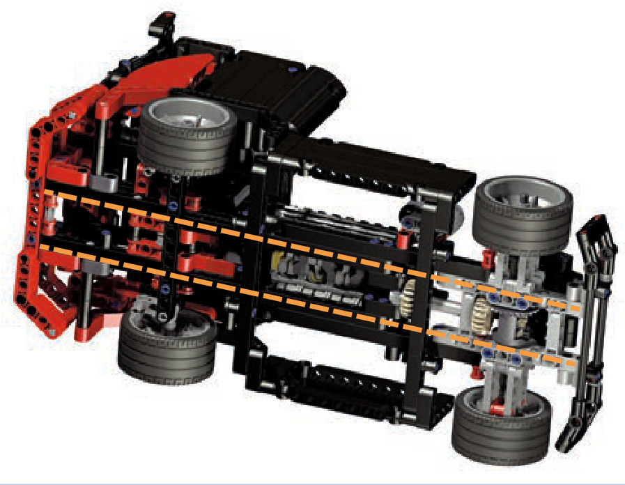
Figure 11-29: The LEGO 8041 set, a small racing truck, is a good example of a model built around two parallel rails.
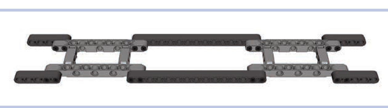
Figure 11-30: A simple combination of rails made of studless beams, with extended body frames working as crossbars. The frames provide space for differentials for front and rear axles, and there is plenty of space between the rails for a propulsion system or a power supply.
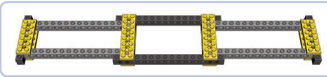
Figure 11-31: A simple studfull chassis combining bricks, pins, and plates
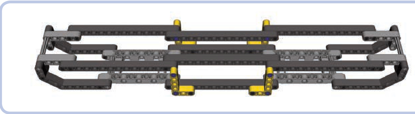
Figure 11-32: A studless body frame with two pairs of rails, one above the other. The upper pair is supported at the ends and in the middle. Studless frames work well with smaller, compact models where adding many elements to the chassis is more important than its rigidity.
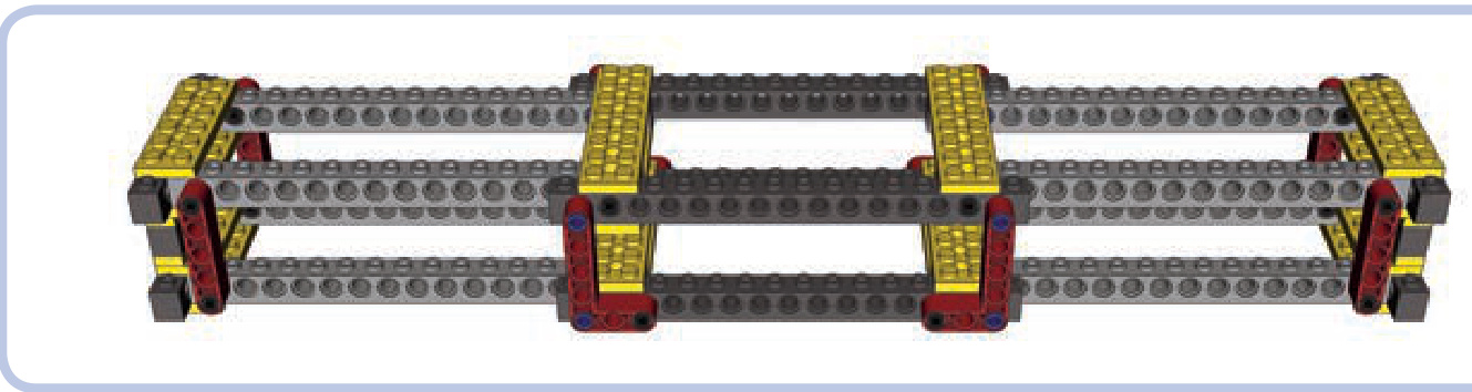
Figure 11-33: A typical studfull body frame, reinforced with vertical beams. This kind of frame works well for big, heavy models where rigidity is of primary importance.
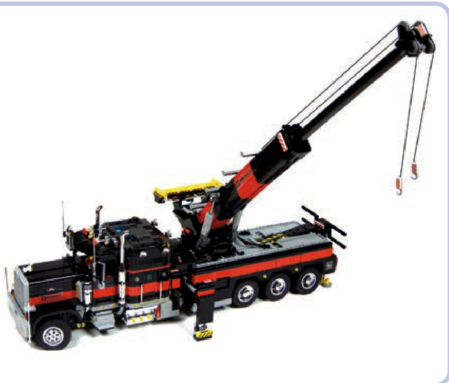
Figure 11-34: My Tow Truck 2 model was very heavy and almost long. It was held together by a massive studfull body frame with two pairs of rails, rigid enough to allow the model to be lifted by hand without any problems. The boom of the truck had its own frame of four studless rails, with the extendable section placed in the middle. It was covered with a studfull shell, which not only made it look better but also improved its rigidity.
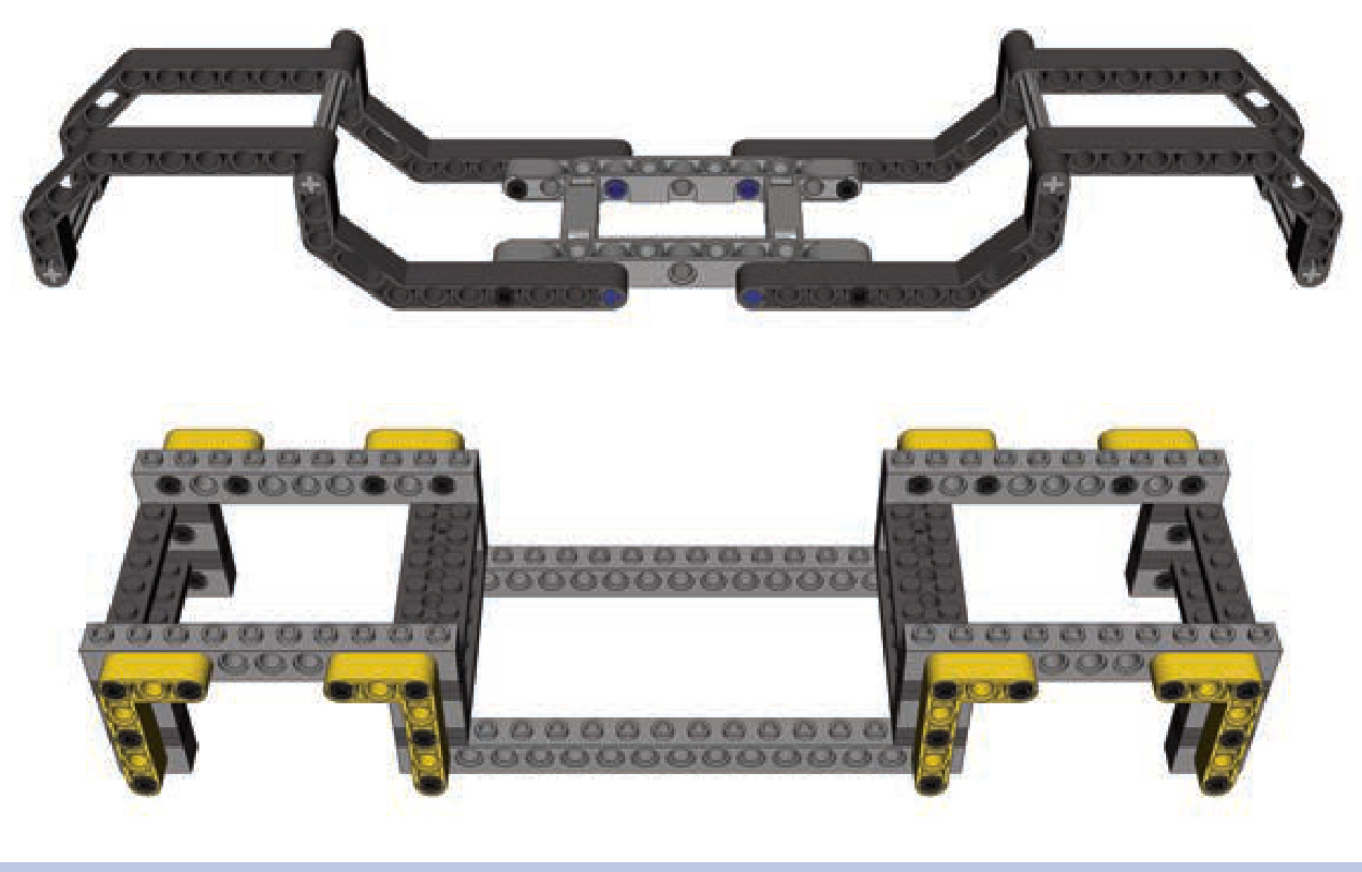
Figure 11-35: Examples of studless and studfull body frames with rails of complex shapes
trusses
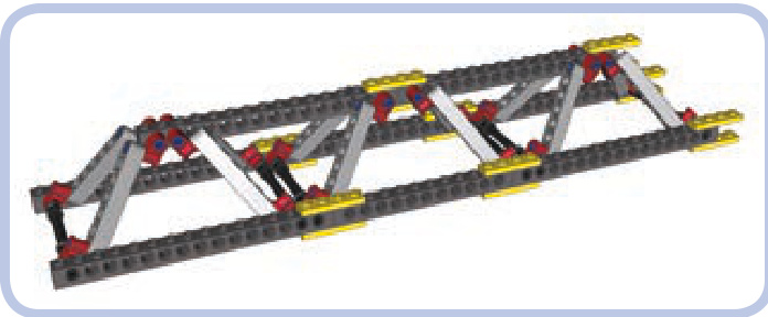
A truss is a particular type of load-bearing structure that consists of beams that form repeated triangles, as shown in Figure 11-36. The triangles are often identical in size, but they don’t have to be. The joints connecting these elements in a truss are often called nodes. Trusses are ubiquitous in the construction of buildings and machines—for example, tower cranes are built almost entirely with trusses. The advantage of trusses is that they can form large, lightweight, and very sturdy structures while using only a handful of basic pieces to build. Figure 11-37 shows a LEGO set that makes use of simple trusses.
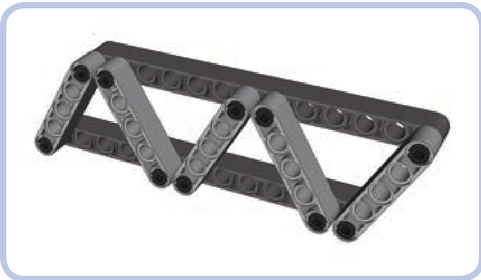
Figure 11-36: A simple truss
Trusses can be divided into two categories: planar trusses, with all nodes within a single plane (like the truss in Figure 11-36), and space trusses, in which nodes extend in all three dimensions (like the truss in Figure 11-38). Space trusses are generally sturdier than planar trusses, and their simple construction allows for modular building. As Figure 11-38 shows, a simple space truss can actually be a combination of two or more planar trusses.
Just like any other load-bearing structures, trusses can be subjected to as many as four types of stress: compression, tension, bending, and torsion, as shown in Figure 11-39. It’s possible to build a truss that can resist all four types of stress, but such a truss is heavy, complex, and takes lots of pieces to build. A more “economical” approach is to choose the type of truss that can handle only the kinds of stress we expect it to experience.
There are more than 20 types of trusses in the world. However, their complex geometry makes many of them difficult to reproduce with LEGO pieces, so we’ll limit our discussion to three practical designs.
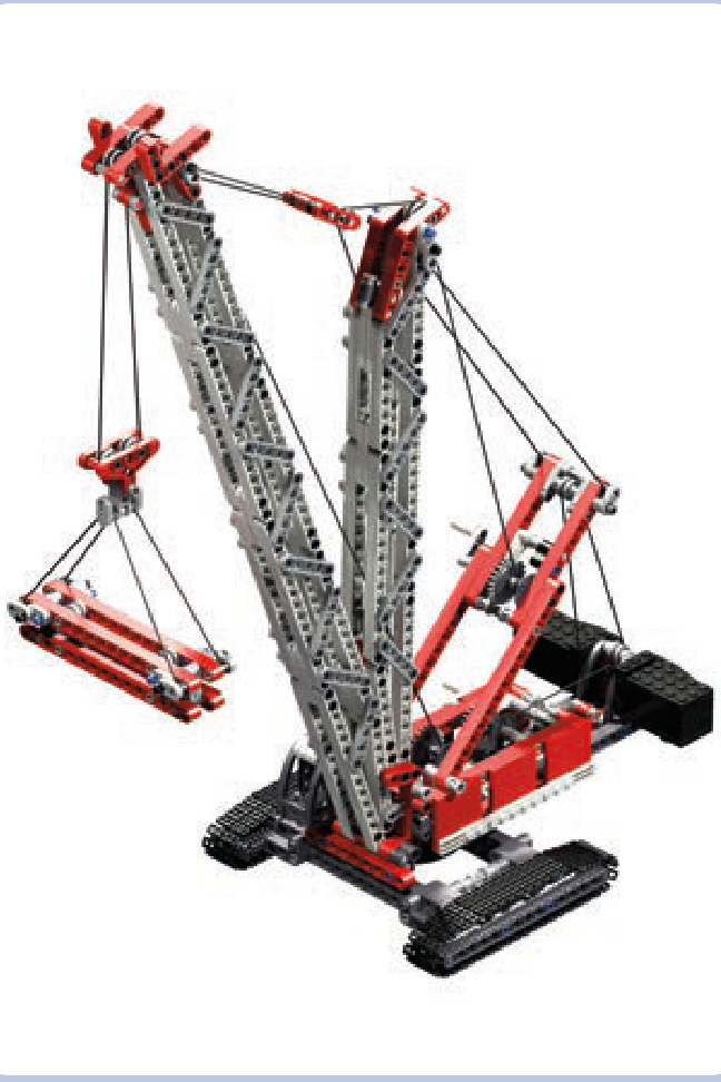
Figure 11-37: The LEGO 8288 Crawler Crane set comes with two booms (greyish in this image) made entirely of simple trusses.
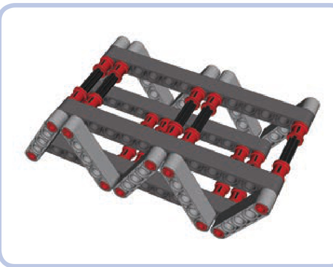
Figure 11-38: Two planar trusses, connected using axles and pins with bushes, create a basic space truss.
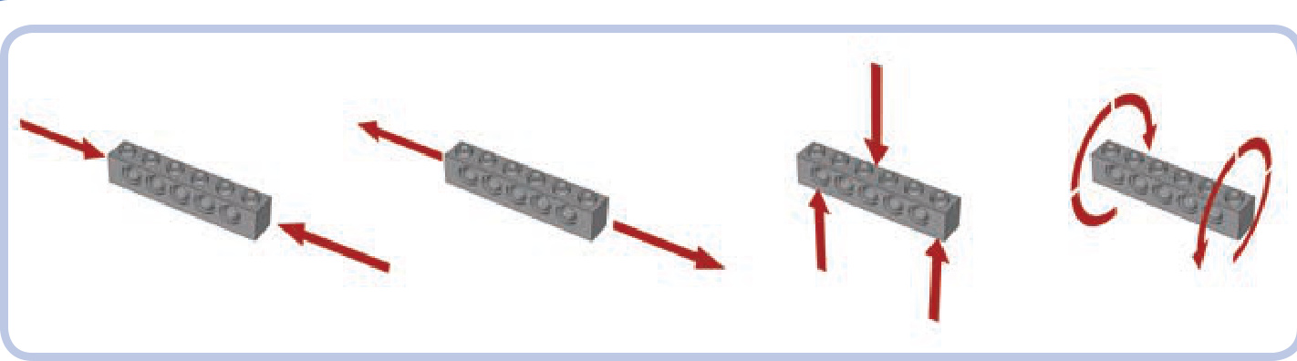
Figure 11-39: From left to right: compression, tension, bending, and torsion
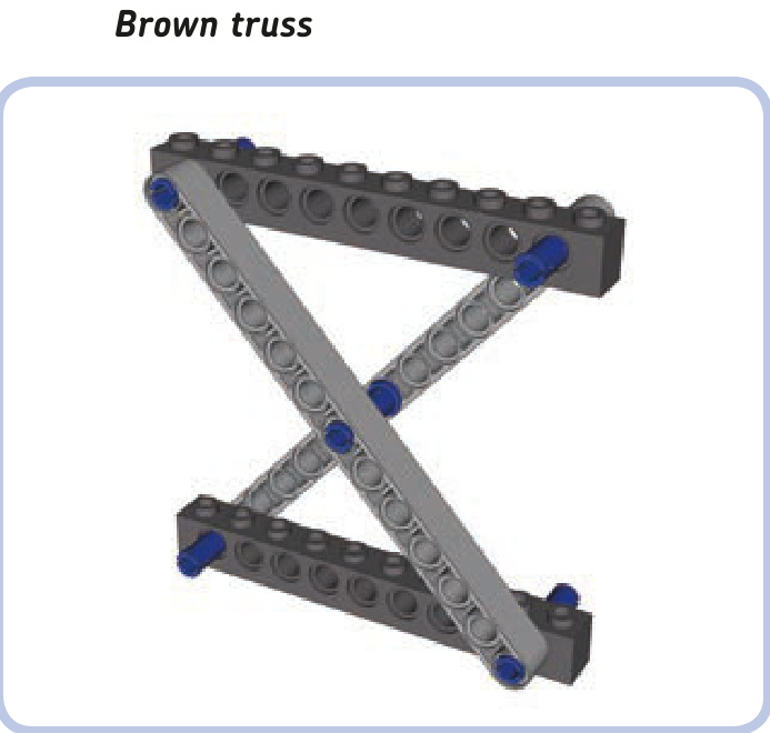
The Brown truss uses an X-shaped reinforcement between two horizontal members. If there is only one reinforcement between these members, its slant beams must be connected in the middle. If there are multiple Xs, this connection is not needed, as shown in Figure 11-40.
The length and angle of beams in the Brown truss module can be adjusted as needed, but the module is strongest with crossbeams exactly perpendicular to each other. Our example above, with 12-stud-long horizontal beams and 13-stud-long crossbeams, is of a convenient size: The gap between the pin holes of the upper and lower horizontal beams is exactly 10 studs tall.
The basic building block of the Brown truss, the planar X, can be combined into planar trusses similar in construction to a scissor mechanism, as shown in Figure 11-40. A more interesting solution is to combine the planar X into a space truss, as shown in Figure 11-41. The space
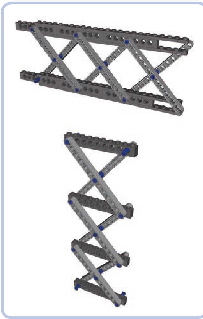
Figure 11-40: Planar combinations of the Brown truss module
combination can also be used to build modules that can easily be stacked on top of one another, as shown in Figure 11-42.
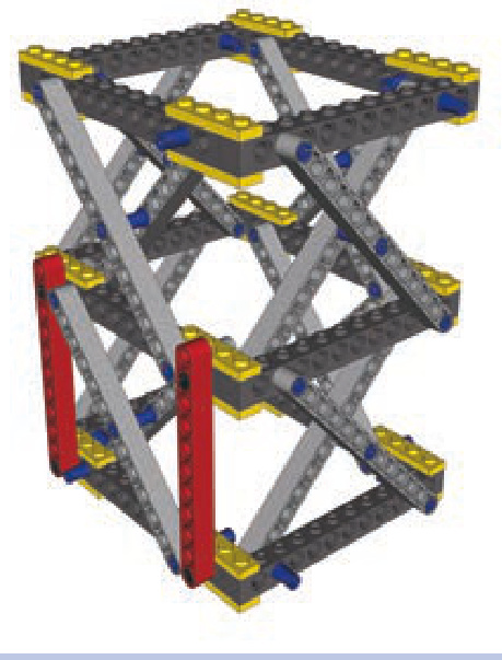
Figure 11-41: Space combination of the Brown truss module. Note that vertical beams (red) can be added for further reinforcement.
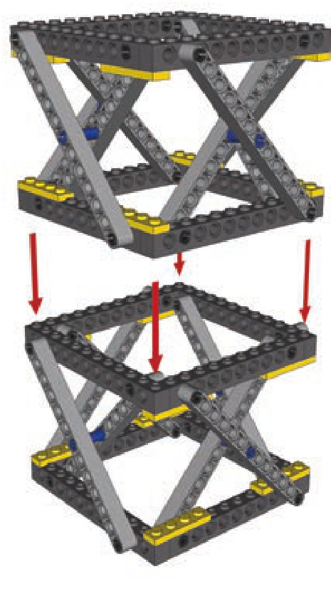
Figure 11-42: The Brown module is shown here combined into space modules that can be stacked on top of one another. This arrangement allows you to easily adjust the height of the resulting structure.
The Brown truss is resistant to compression and torsion. Its resistance to tension and bending depends on the strength of connections between its modules.
Warren truss
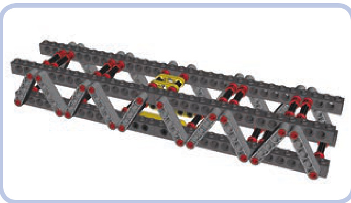
The Warren truss combines two simple planar trusses. The length and angle of the slanted beams (light grey) can be adjusted as needed. The slanted beams also don’t have to be adjacent—small gaps between them are acceptable. The horizontal beams (dark grey) can be studless, as in Figure 11-38, or studfull, as shown above (in which case they can be further reinforced with plates).
The Warren truss is resistant to compression, tension, and bending. Torsion affects connections between its planar trusses and can lead to disintegration.
triangular Warren truss
The triangular Warren truss, shown in Figures 11-43 and 11-44, combines two simple planar trusses to form the shape of a triangular prism. The truss has two lower beams but only one upper beam, which makes it weigh less than the regular Warren truss, though its construction requires additional connectors (red in the illustration and in Figures 11-43 and 11-44). This variant is nearly as robust as the regular Warren truss, except that its lower beams are subjected to more stress than the upper beam. Also, pressure on the upper beam can push the two lower beams apart unless they are connected (by perpendicular plates, for example).
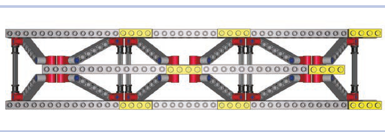
Figure 11-43: Top view of the triangular Warren truss
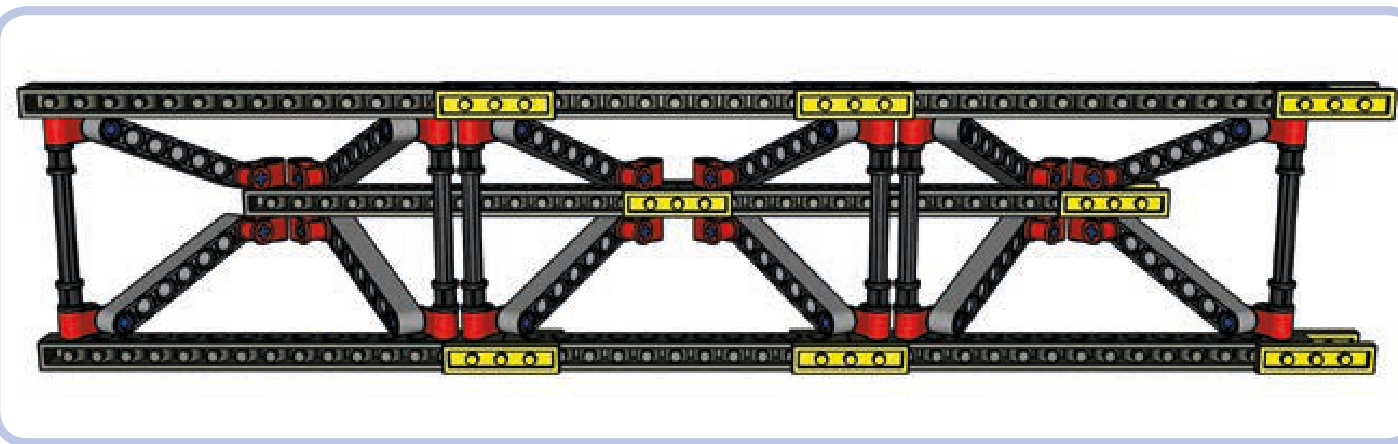
Figure 11-44: The bottom view of the triangular Warren truss shows that the lower beams (horizontal, top and bottom) are held together only from the inside of the truss. This means that they can be pushed apart by a sufficiently high load on the top beam (horizontal, middle).
The triangular Warren truss is resistant to compression tension, and bending. With lower beams firmly connected by crossbeams, it is also considerably resistant to torsion.
choosing the right truss
its chassis, as shown in Figure 11-45. This means that the chassis is subjected to bending. A regular Warren truss will easily handle that stress while also resisting the minor compression and tension that occur when the bus starts and stops.
A truss made of firmly connected Brown modules can withstand all types of stress. It is, however, complex and heavy, so we’ll only want to use it if it’s absolutely necessary. This section explores how to determine which truss will work best for various vehicles.
Let’s first consider a bus, which has a large gap between its front and rear axle. Its axles support it from the bottom, while its weight presses from the top on the middle of
An off-road truck, on the other hand, is less subject to bending due to its shorter length. But such a truck is designed to negotiate difficult obstacles, which will make its suspension work hard, making the wheels go up and down. It’s very likely that the front and rear axles of our truck will oscillate in opposite directions while traversing an obstacle, which will exert torsion on the chassis, as shown in Figure 11-46.
Figure 11-45: Forces exerted on the chassis of a bus. The chassis is primarily subjected to bending.
Figure 11-46: Forces exerted on the chassis of an off-road truck. The chassis is subjected primarily to torsion but also to bending.
We can use Brown modules in our truck’s chassis if we want it to be extremely sturdy, but we can also use the triangular Warren truss to save some weight and space. With its lower beams held together, the triangular Warren truss will handle both torsion and bending.
Our last example is a tower crane, which has several elements that could use reinforcing. We’ll see how different sections of the crane will benefit from using different kinds of trusses.
As Figure 11-47 shows, we can break our crane into four parts. First is the part that supports the entire crane, called the tower mast (yellow). As the weight of the crane rests on it, the tower mast is subjected to compression. Lifting loads also makes the crane tip a bit, so the structure is subject to some bending. Finally, the upper portion of the crane can rotate while the yellow truss remains fixed to the ground—this exerts torsion when rotation starts and stops. So we know our yellow tower mast truss must withstand all types of stress except tension. A truss made of space Brown modules will be a good choice.
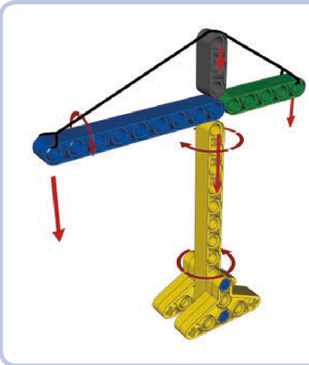
Figure 11-47: Forces exerted on various parts of a tower crane
Our second truss (blue) is called the jib. It’s the part directly responsible for moving loads. As one end is fixed to the center of the crane, the other has loads suspended on it and is supported by a cable called the jib tie, which exerts some compression on it. As the crane rotates, the loads swing a little below the jib, exerting some torsion on it as well. Note that the jib is the second-largest part of the crane, and it can add a lot of weight. We want the jib to weigh as little as possible, so the triangular Warren truss will be a good choice here, resisting both compression and torsion while adding less weight than other options.
The third part (green) is called the counterjib. The counterjib is fixed to the center of the crane at one end and supports the crane’s counterweight at its other end. It is therefore subjected to bending, just like the jib, but to a smaller degree because of its shorter length. Its counterweight doesn’t swing during rotation, so it isn’t subjected to torsion. We can use the triangular Warren truss here as well, or we can instead choose the simpler regular Warren truss—the counterjib is so short that the difference in weight will be minimal.
Finally, the grey part, called the top mast, simply supports the cable that connects opposite tips of the jib and counterjib. The jib tie exerts compression on the top mast and slight bending on the counterjib, which we’ve already accounted for. The top mast is small and little stress is involved, so we can use a small section of the Warren truss; alternatively, we can give up on trusses and use any structure capable of supporting some weight put directly on top of it. Figure 11-48 shows an example of a real tower crane built the same way as our model.

Figure 11-48: A real tower crane at work. As you can see, its tower mast is built with a Brown truss, and its jib is built with a triangular Warren truss, just like in our model.
choosing the strongest pieces
Although LEGO pieces are known for their lasting quality, they are prone to aging and wear. This means there are two things you should avoid when picking pieces for a tough job: aged pieces and physically worn pieces.
It’s safe to assume that LEGO pieces fully maintain their quality for at least 5 to 10 years, unless damaged. As your collection ages, or is supplemented with older pieces and garage sale treasures, you should carefully select the pieces that will handle high stress. The easiest way to determine a piece’s age is to keep a few new pieces for comparison. LEGO pieces, particularly white and grey pieces, yellow over time. Figures 11-49 to 11-51 show the difference.
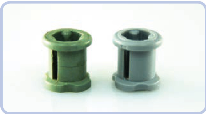
Figure 11-49: A bush: roughly 20 years old (left) and 1 year old (right). Note the crack in the old bush’s side; under torque, this crack will soon lead to the bush’s disintegration.
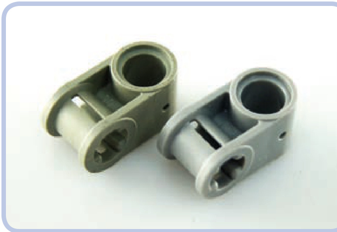
Figure 11-50: A connector: old (left) and new (right). Even though the old piece is free from damage or visible wear, the difference is obvious.
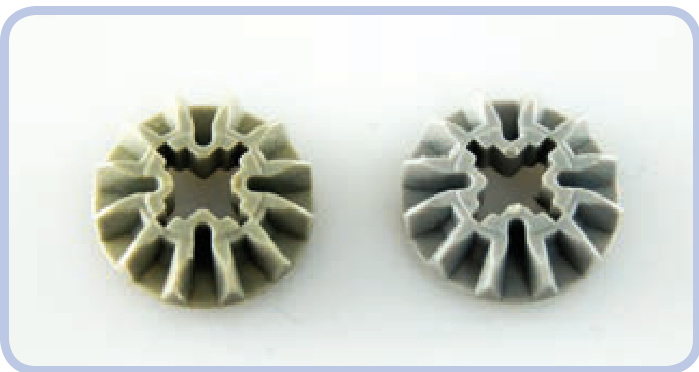
Figure 11-51: Two gears of the same type made roughly 10 years apart
Pieces that are physically worn aren’t too difficult to spot. The wear can vary from very subtle—negligible for our purposes—to obvious damage. You should look for wear on the surfaces that contact other pieces, such as the teeth of gears or the area around the pin hole in a brick. Wear occurs more often on pieces that are subjected to high stress, such as knobs, small gears that are crucial for high gear reduction, or various pieces that work with worm gears. Figures 11-52 to 11-54 show typical examples of wear.
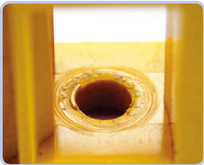
Figure 11-52: A close-up view showing the inside of a LEGO casing for a worm gear. Here, a worm gear has partially drilled into one of the casing sides.
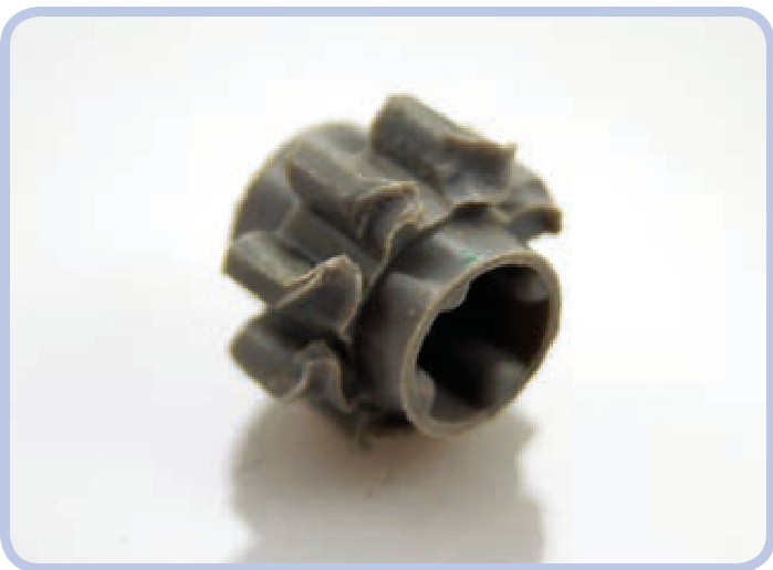
Figure 11-53: This gear’s teeth were ground away when it was misaligned to a larger, stronger gear. While the piece itself is new and most of it remains intact, this kind of wear makes the gear unusable.
Figure 11-54: This visibly worn knob has polished edges where the material has been rubbed away. Knobs transfer high torque over very small areas of contact, resulting in intense wear. Worn knobs produce a distinctive squeaking when working under stress.
Finally, note that differently colored pieces actually have different properties. The exact variations are difficult to measure, but I have observed that red pieces are particularly weak while yellow pieces are particularly strong. The difference isn’t big, but it can manifest when pieces are subjected to prolonged stress.

12
an inventory of LEGO motors
Electric motors are the muscle of most Technic creations. While it’s perfectly fine to build mechanisms driven by hand, and some builders actually specialize in human-powered models, the most impressive constructions are motorized. Motors can be used for almost anything, from driving and steering to rotating, elevating, extending, and even controlling other electric components. In this chapter, we’ll explore which LEGO motors are best suited for which purposes.
LEGO has been making electric motors since 1965, and they can be classified into three general categories. The first motors were motors, but they’re rare, old, and inferior when compared to the newer motors, so let’s move straight to the next category.
In 1990, LEGO introduced a second line of motors, running at 9V on six AA batteries (shown in Figure 12-1). These motors are considerably more powerful and convenient to use than their predecessors. The 9V line also has greater variation, including motors for boats with propellers and
watertight housings. The 9V motors are widely available and highly popular. We’ll discuss this line of motors in this chapter, with the exception of some specialized ones, such as the Trains and Monorail motors, which are very difficult (or downright impossible) to use outside their intended applications.
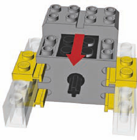
The third category of motors is the Power Functions line, introduced in 2007 (shown in Figure 12-2). These motors are designed to use a 9V power supply as well, but unlike the previous category, they are part of a carefully planned and currently developed system of motors and specialized parts. The Power Functions line includes just a few motors, which are designed to complement each other. Each motor is suited for different tasks, and the characteristics of the motors vary considerably. PF motors are well suited to studless building because they have odd widths and pin holes, and their torque is optimized for high-load applications. Additionally, they can be controlled remotely, while the motors in the other two categories can be controlled only with a wire connected to the power supply, which acts as a controller. Power Functions motors also allow more finegrained control, with more options than simply forward and reverse. We’ll explore the Power Functions system and its controls in Chapter 13.
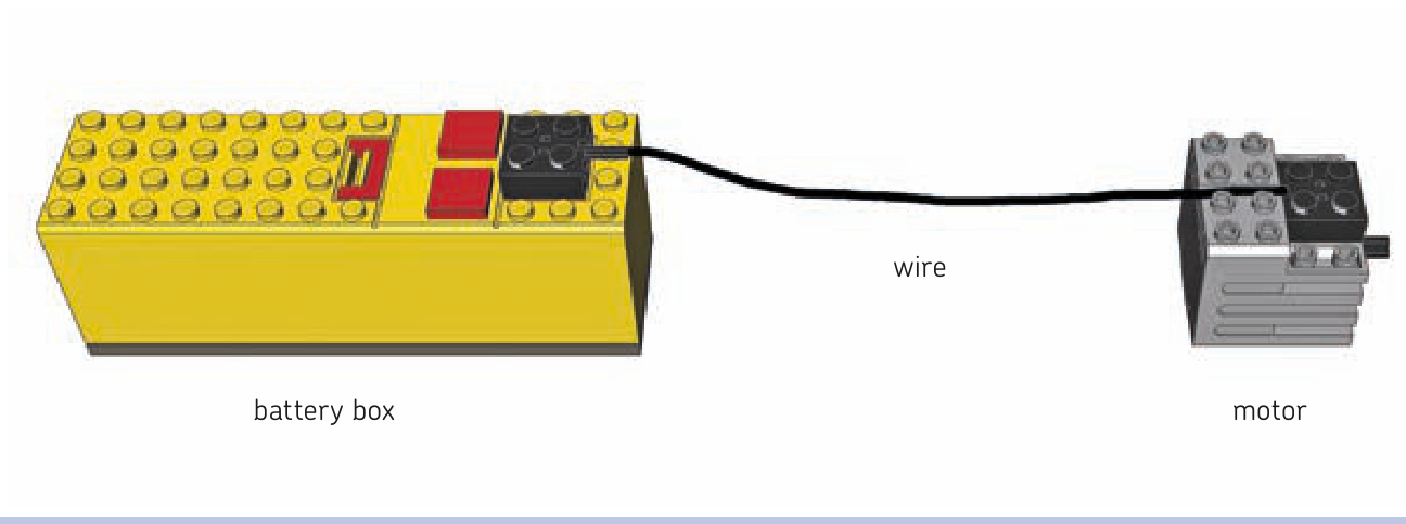
Figure 12-1: The 9V line is powered by a battery box, which also functions as a basic switch.
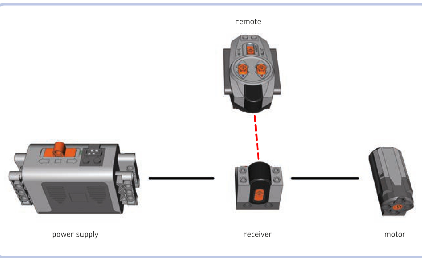
Figure 12-2: The Power Functions motor system can be controlled remotely.
The following list includes speeds of motors at both 9V and 7V whenever such data is available. (Rechargeable AA batteries and the rechargeable Power Functions battery provide a 7V power supply.) Also, note that motors are prone to wearing down over time; thus, the exact characteristics of any two motors of the same type can vary.
While there is no official technical specification for the LEGO motors, LEGO enthusiast Philippe “Philo” Hurbain has spent a lot of time performing many complex measures on these motors. This chapter’s measurements are derived from his work and used with his kind permission. (Read more about Philippe’s work at his site, http://www.philohome.com/ motors/motorcomp.htm.)
2838, the first 9V motor
Torque: 0.45 N•cm No-load speed at 7V: 2000 RPM No-load speed at 9V: 3300 RPM
The first motor in the 9V line, the 2838, is relatively large and has no internal gearing, which results in very high speed and low torque. It’s ineffective in high-load applications where it requires substantial gear reduction, often including one or more worm gears. This motor is also prone to overheating. The motor has a 1L axle protruding out of it and connects to the power supply through a contact area in the middle of its bottom surface.
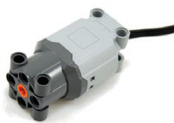
71427, a popular and powerful 9V motor
Torque: 2.25 N•cm No-load speed at 7V: 160 RPM No-load speed at 9V: 250 RPM
This 9V motor is popular due to its reasonable size and favorable characteristics. It’s a very quiet motor with substantial internal gearing, which creates noticeable inertia when the motor is stopped. The motor has a 1L axle and connects to the power supply through a contact area on its top. Its upper surface is conveniently shaped, with one recess for the power plug and another for routing the wire backward. Its lower surface has a 1-plate-tall bulge in the back.
43362, a lighter 9V motor
Torque: 2.25 N•cm No-load speed at 7V: 140 RPM No-load speed at 9V: 219 RPM
Externally identical to the 9V 71427 motor (shown previously), this motor is almost one-third lighter at the expense of slightly reduced speed. The difference in weight makes it more sought after than the original 71427 motor, so it sells for significantly higher prices. The motor has a 1L axle and connects to the power supply through a contact area on its top. Its upper surface is conveniently shaped with one recess for the power plug and another for routing the wire backward. Its lower surface has a one-plate-tall bulge in the back. Just like the 71427 motor, this motor can be mounted on rails using the two slots on its sides (shown in Figure 12-3).
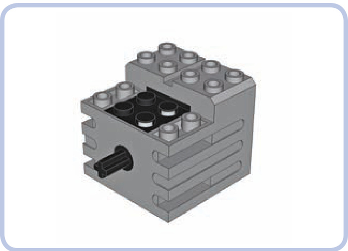
Figure 12-3: The slots on the sides of the 43362 motor fit plates with rails. The motor can be firmly secured using two of these (or more). As shown by the red arrow, the motor must be slid onto these plates with rails.
47154, a 9V motor in a semitransparent housing
Torque: 2.25 N•cm No-load speed at 7V: 210 RPM No-load speed at 9V: 315 RPM
This motor is similar to the 71427 motor, except that it has a higher speed and is louder. It’s 1 plate taller than the 71427 motor and comes with a completely flat bottom. The motor has a 1-stud-deep axle hole and connects to the power supply through a contact area on its top.
Micromotor
Torque: 1.28 N•cm No-load speed at 9V: 16 RPM
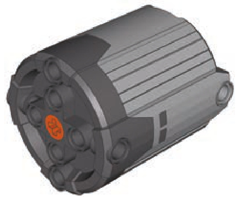
This 9V motor is exceptional for its small size. It’s rare, highly sought after, and expensive. Its speed is so slow that it doesn’t usually need external gear reduction, while its torque is quite high for a motor this size (higher than the 2838 motor’s torque, for example). A complete Micromotor consists of four individual pieces: an upper and lower brace, a “Micromotor pulley,” and the motor itself. The motor is rarely used without these pieces, although it can be operated without the braces if it is connected to something by its power plug. The motor connects to the power supply through a contact area at its back. Figure 12-4 shows an exploded view of the Micromotor and its parts.
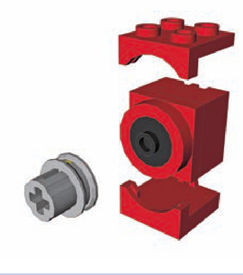
Figure 12-4: An exploded view of the Micromotor, showing its upper and lower brackets, pulley, and motor
The Micromotor’s specially designed pulley has a 1-stud-deep axle hole and a belt groove for a rubber band. The pulley allows the motor to be connected to an axle. The pulley also works like a slip clutch, preventing the motor from stalling.
NXT motor
Torque: 16.7 N•cm No-load speed at 7V: 82 RPM No-load speed at 9V: 117 RPM
Power Functions E motor
Torque: 1.32 N•cm No-load speed at 7V: 300 RPM No-load speed at 9V: 420 RPM
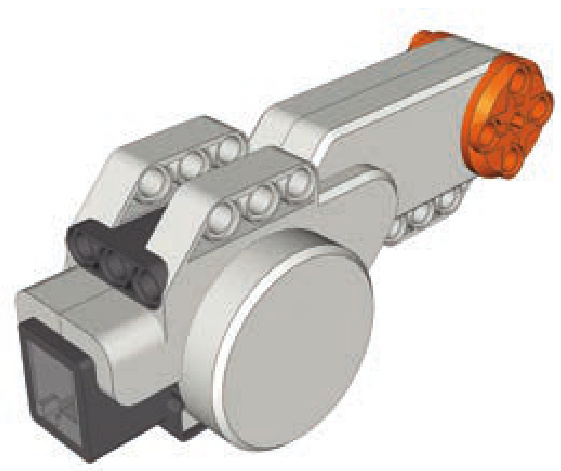
This motor was designed specifically for the MINDSTORMS NXT set. It has the highest torque of all existing electric LEGO motors and high power consumption. It includes a rotation sensor with a one-degree resolution, which is useful when designing robots that require precise control.
However, its shape and size are a disadvantage when one is using it outside MINDSTORMS constructions, and it connects to the power supply through a MINDSTORMS-type plug, which means that a special converter cable is required to connect it to regular 9V or Power Functions power supplies. Unlike other motors, its output is a 3-stud-wide ring (orange in the figure above) with four 1-stud-deep pin holes around the center. It also has an empty axle hole in the center through which any axle longer than 3 studs can be inserted.
This unusual Power Functions motor was designed for LEGO Education sets. It has low internal gearing, which allows it to be easily driven and to act as a power generator. However, its large size and poor speed and torque performance make it practically useless when compared to other Power Functions motors. The motor has a 1-stud-deep axle hole and an integral wire.
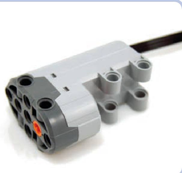
Power Functions Medium (M) motor
Torque: 3.63 N•cm No-load speed at 7V: 185 RPM No-load speed at 9V: 275 RPM
Power Functions L motor
Torque: approx. 6.48 N•cm No-load speed at 7V: 203 RPM No-load speed at 9V: 272 RPM
With a diameter of only 3 studs, this popular Power Functions motor takes up little space and fits studless constructions exceptionally well while offering very good torque. The only downside to this motor is that it’s 6 studs long; other than that, it’s easy to use, powerful, and versatile. This motor has a 1-stud-deep axle hole and an integral wire. It can be mounted either from the front using some of its four pin holes or from the bottom using studs.
Introduced in 2012, the L motor works where the Medium motor is too weak and the XL motor is too big. At studs it’s only slightly larger than the Medium motor, while delivering nearly 180 percent of Medium’s torque. It’s a little slower than Medium motor though, and its power consumption is higher (see “Understanding the Speed Control Feature” on page 177 for details). This motor has a 1-studdeep axle hole and an integral wire. It can be mounted from the front or back, or from two of its sides using pin holes—it has 14 of those, including 2 at the back.
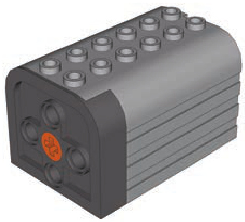
Power Functions XL motor
Torque: 14.5 N•cm No-load speed at 7V: 100 RPM No-load speed at 9V: 146 RPM
This is the most powerful Power Functions motor. It shares some essential internal parts with the NXT motor but has lower torque and higher speed. The XL motor is popular because it’s extremely powerful, and it’s more prevalent and easier to use than the NXT motor. Still, its large size makes coupled Medium motors a better choice in many cases. This motor has a 1-stud-deep axle hole and an integral wire.
This motor cannot be connected via studs. It has six axle holes on its front and four on its sides, which allow it to be firmly braced in a construction against considerable output torque.
Power Functions Servo motor
Introduced in 2012, the Servo motor is designed for steering systems. It can’t rotate continuously—instead, it rotates 90 degrees clockwise or counterclockwise from its central position. Its low speed allows it to be used with most steering systems directly, with no gearing in between, while its huge torque makes sure it won’t be easily stalled.
When used with a basic PF remote, the Servo motor rotates 90 degrees in one direction or the other when the remote’s lever is pushed, and it returns to the central position when the lever is released. When used with the speed control PF remote or directly with the rechargeable PF battery, the motor follows the rotation of the speed dial, meaning that it provides proportional steering with 7 steps in either direction and 1 neutral position (which it returns to after the remote’s stop button is pressed). In other words, it uses the PF speed control feature to break its 180 degrees of total rotation range into 15 steps, 12 degrees each, while its speed remains constant at all times.
This motor measures studs, and it has a bulge on its bottom with a 1-stud-deep axle hole on the front and another on the back. Thus, the motor can be inserted between two axles; it will keep them 1 stud apart and rotate them as one in the same direction. It also has an integral wire and can be mounted from the front or from two of its sides using pin holes.
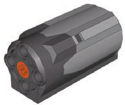
RC motor
Torque (inner output/outer output):
No-load speed at 7V (inner output/outer output): 906 RPM/670 RPM
No-load speed at 9V (inner output/outer output): 1245 RPM/920 RPM
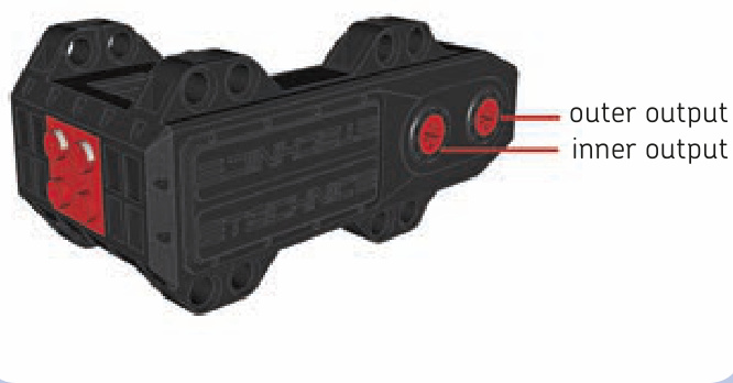
This 9V motor was originally designed for a discontinued series of fast radio-controlled cars. As such, it has an unusual shape, good torque, and very high speed. Unfortunately, it is also very noisy and has extremely high power consumption; in fact, some power supplies can’t even let it run at full power. In theory, its speed and torque make it the most powerful electric LEGO motor, and with efficient external gearing, it can perform better than XL or NXT motors. It does, however, tend to become overheated under high loads, which causes its internal electronic protection to shut the power off until the motor cools down.
The RC motor is unique because it has two outputs. Both are empty axle holes running in the same direction, but the motor’s internal gear ratio is different for each of them. Because of this, the inner output runs faster at lower torque than the outer one.
13
LEGO Power Functions system
The LEGO Power Functions system (or PF for short), introduced in 2007, is a combination of LEGO elements that allows you to motorize your constructions, to equip them with lights, to move them with linear actuators, and, above all, to control them remotely. In this chapter, we will learn how this system works and how its elements can be combined.
The core parts of the Power Functions system can be divided into three groups: power supplies, control elements, and motors. There are several types of motors in the Power Functions system, and all of them are described in the previous chapter. The Power Functions system allows us to control motors with more flexibility, offering fine-grained control of speed and the ability to control multiple elements at once.
Not e One of the novelties of the Power Functions system is that the majority of its elements have been released as stand-alone, separate LEGO sets. A list of these sets can be found at the end of this chapter.
manually controlling motors
To control a motor by hand with Power Functions system, you need only two elements: a power supply and a motor, as shown in Figure 13-1. All Power Functions power supplies come with controls on them, some basic and some advanced, and these controls affect any and all motors directly connected to the power supply.
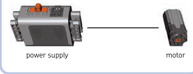
Figure 13-1: The simplest Power Functions motor configuration
Note that the plugs of the Power Functions wires are stackable, and we can connect many wires to a single outlet, as shown in Figure 13-2.
Figure 13-2: A regular Power Functions battery box with three plugs stacked on its outlet. Three elements can now be powered and controlled from this box at the same time.
The simple power supply and motor configuration has one serious disadvantage: If many motors are connected to one power supply, they will all work as one. This is inevitable when using the power supply as a control mechanism, which is why the Power Functions system includes a separate group of control elements. The simplest element from this group is a switch, shown in Figure 13-3.
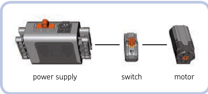
Figure 13-3: A slightly more complicated configuration for the Power Functions system
Just like all control elements, the switch is connected between the power supply and the element we want to control. It has three positions—forward, stop, and reverse—and they affect all elements connected to the switch.
Note that in this configuration, the controls of a switch and the regular battery box can work at the same time, so either can be used to control the motor. (But if the power supply is set to off, obviously, the setting of the switch won’t affect the motor.)
remotely controlling motors
While direct manual control is a nice option, the key advantage of the Power Functions system is the ability to control motors remotely. This is done by a pair of elements: a remote and a receiver (see Figure 12-2 on page 164).
You can think of the remote and receiver as a switch split into two parts. One part, the receiver, is between the power supply and the elements we want to control, just like a switch. It also has a wire just as a switch does. The other part, the remote, has no wires and isn’t physically connected to anything. It sends commands to the receiver using an invisible infrared link, just as most TV remotes do. It also houses batteries, just as TV remotes do, so it needs no external power supply. Your construction, with the receiver integrated into it, can be controlled from a distance using the remote.
It’s important to remember that the infrared link between remote and receiver has its limitations. The black, semitransparent parts of both remote and receiver house infrared sensors that need to be exposed and within a line of sight of each other to maintain a link. The remote is actually sending out invisible light signals, and they won’t reach the receiver if something blocks their way or if they are sent in the wrong direction. They can, however, bounce off walls and ceilings; so as long as you remain indoors, pointing the remote in the receiver’s general direction is sufficient. You can also cover up the receiver almost entirely in constructions intended for indoor use, as Figure 13-4 shows. A opening around or slightly above the receiver’s top will do the job. Outdoors, maintaining the link between remote and receiver is more difficult: The remote has to be aimed with good precision, and its range can drop to as little as if the receiver’s sensor is exposed to strong sunlight.
Figure 13-4: An IR receiver doesn’t have to make your construction ugly. You can cover it up almost completely, leaving only the opening around the sensor. The cover can end up level with the sensor or even slightly above it and still work, as long as you hold the remote higher than the receiver.
As Figure 13-5 shows, a receiver has two levers, one blue and one red, along with two outlets colored the same way. The levers and outlets correspond—the blue lever controls everything connected to the blue outlet, while the red lever controls everything connected to the red outlet. The remote comes with two pole reversers, one for each outlet/ lever. The reversers’ function is simple: They determine whether pushing a lever forward makes a motor connected to the corresponding outlet rotate forward or in reverse. The blue/red elements are independent and can work at the same time. In other words, the blue lever doesn’t interfere with the red lever, and the blue pole reverser doesn’t interfere with the red pole reverser.
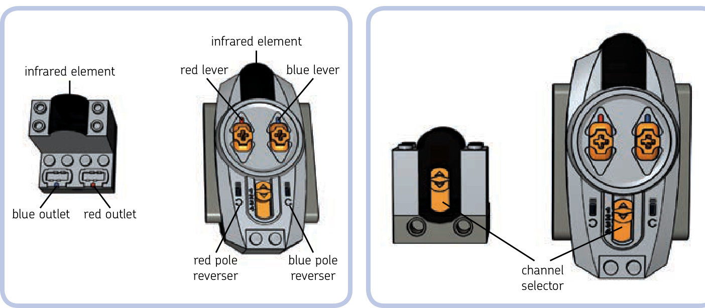
Figure 13-5: The receiver and basic remote
There is a reason why we said that a lever controls everything connected to its corresponding outlet. Since the Power Functions plugs are stackable, you can connect as many motors or other elements to an outlet as you want—all of them will be controlled simultaneously by the corresponding lever. This means that you can control more than two motors using a single receiver, and the motors connected to the same outlet will work as one. For example, you can drive your vehicle with two motors together when one is too weak, or you can have the headlights in your vehicle turn on as it drives.
Not e The actual number of elements that can run off a single power supply simultaneously is limited by their total power consumption. If it becomes too high, the power supply shuts down. This is most likely to happen with motors and least likely to happen with LEDs.
This limits us to controlling two functions independently per one individual receiver. We can, however, control more functions using many receivers and just a single remote. As Figure 13-6 shows, both receiver and remote come with a simple orange switch called a channel selector. It has four positions numbered from 1 to 4. With a channel selector, we can use a single remote with up to four receivers.
Imagine that we have four receivers, each set to a different channel: the first receiver set to channel 1, the second to channel 2, and so on. If you set the channel selector on the remote to 1, only the first receiver will react to the remote and the other three will not. Similarly, if you set the remote’s selector to 2, only the second receiver will react to it; if you set it to 3, only the third one will react; and if you set it to 4, only the fourth one will react. This way you can control up to eight functions independently with a single remote, but since the remote can only be set to one channel at a time, you can control only two functions at the same time. Controlling another two functions requires switching the remote’s channel selector to a different position. Figure 13-7 shows the 1 remote / 4 receivers / 8 motors arrangement.
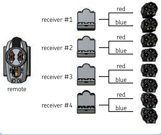
Figure 13-6: The channel selectors on a receiver and basic remote
Figure 13-7: Each receiver is set to a different channel and has one motor connected to each of its outlets. In this way, eight motors can be controlled independently.
Controlling just two functions simultaneously is clearly a limitation—but one that can be overcome with additional remotes. You can use many remotes at the same time, even four, each tuned to a different channel. Many builders prefer to use several remotes at once rather than a single remote that needs switching between channels. It’s even possible to use many remotes set on the same channel with a single receiver, for example, to let several people control the same construction.
Note that when many remotes are sending commands at various channels at the same time, receivers react more slowly. This is because each receiver reads commands from all four channels all the time, and its channel selector tells it only which to ignore and which to accept. When there are many commands to read simultaneously, the receiver is slowed down.
Now that we know how the Power Functions system works, let’s take a look at its individual elements.
power supplies
The power supplies of the Power Functions system come in several variants, allowing us to choose between two types of batteries or even freeing us from the need for regular batteries at all. Every power supply can have many elements connected to it, but if too many elements are running off a single supply simultaneously, the electronic counter measures in it will shut it down. This is most likely to happen with power-costly elements, such as motors. When it does, simply turn the supply off and on again.
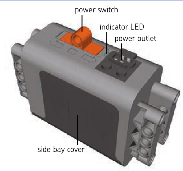
AA battery box
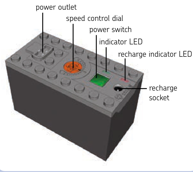
This simple box contains six AA batteries, with two side bays for three batteries each. The box is studs, with an orange power switch protruding by 1 stud on top of it. The switch has three positions—forward, stop, and backward— and the indicator LED adjacent to the switch shines green on the first and last position. The box is completely studless and connects by pin holes on its sides.
AAA battery box
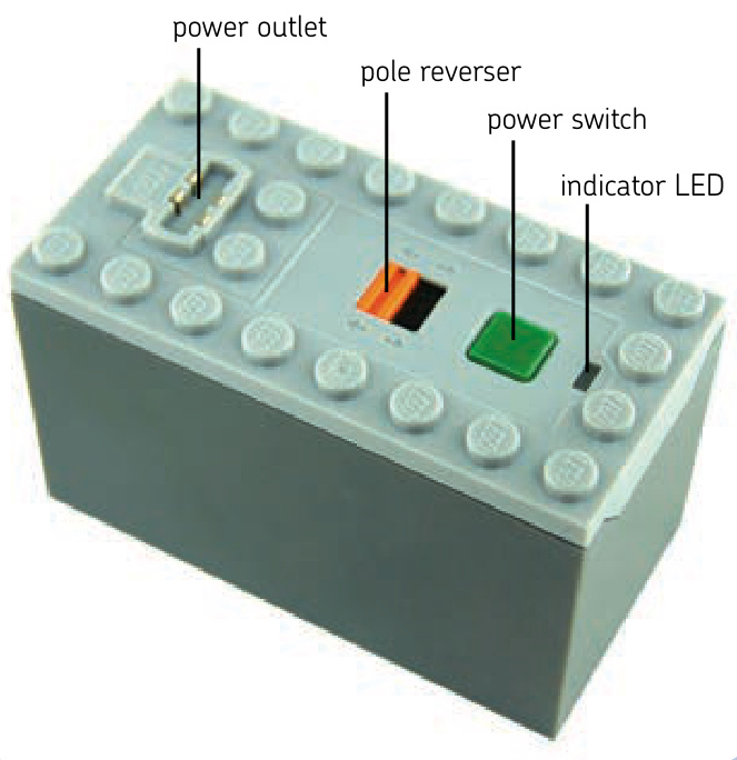
The box contains six AAA batteries, which are inserted by unscrewing the box’s bottom. The box is studs, with a studfull bottom and top. Its power switch has the form of a simple green button. Pushing the button toggles the box between on and off. The box also has an indicator LED that shines green when the box is on and a simple orange pole reverser that determines whether turning the box on makes motors connected to it run forward or backward. The AAA batteries are smaller and lighter than AA ones; they can’t power as many elements simultaneously, and they last roughly a third as long.
Not e This box comes with a timer: Once turned on, it will turn itself off after 2 hours. You can stop the timer by holding the power switch down for 3 seconds. Turning the box off and on again resets the timer. This feature, intended to prevent the batteries from running dry if we forget to turn the box off, can be mistaken for a malfunction or battery failure.
rechargeable battery
This self-contained battery with rechargeable power cells can be recharged using a transformer, without the need for replaceable batteries of any type. It’s studs, with a studfull bottom and top. Unlike regular battery boxes, it does not open. Its power switch has the form of a simple green button, and pushing it toggles the battery between on and off. Next to the power switch, there is an indicator LED that shines green when the battery is on and an orange speed dial with 15 positions: 7 forward, 7 backward, and 1 stop position. Turning the dial controls the speed of all motors and the brightness of all lights connected to the battery. It does not affect receivers connected to it. On the other side of the power switch, there is a recharge socket for the transformer, and an adjacent indicator LED blinks red during recharging and shines red when recharging is complete.
The battery houses two lithium ion polymer cells with a total capacity of , providing a constant voltage of 7.4 V. The LEGO Group recommends recharging it with a dedicated transformer, sold separately, and defines the full recharge time as 4 hours.
While costly, the battery can be attractive to builders who use plenty of standard batteries. It allows them to build lighter and simpler because it weighs under (the AA battery box can weigh over , depending on the batteries’ make). This battery can also be integrated into your construction permanently, with only a -stud opening to access its power switch and recharge socket. It provides lower voltage than standard batteries do (9 V) but higher voltage than rechargeable AA batteries do . Its capacity is smaller than that of most AA batteries, meaning that it runs dry more quickly, but it makes up for this by never needing a battery replacement. When empty, it can be recharged inside your construction by simply connecting the transformer to it, while the battery boxes usually need to be taken out of your construction to replace batteries.
Not e This battery also comes with a timer: Once turned on, it will turn itself off after 2 hours. Unlike the timer in the AAA battery box, this timer can’t be stopped. Turning the battery off and on again resets the timer.
receiver
The Power Functions receiver, shown in Figure 13-8, is studs and requires at least a half stud of space at the back for plugs connected to it. It has a studfull bottom and top and two pin holes in front. It also has a four-position channel selector in front and an indicator LED adjacent to it, which shines green when the receiver is under power and blinks when the receiver accepts commands from its selected channel.
In 2012, a version with upgraded electronic components was released. This version is distinguished by the printed on the front (see Figure 13-9) and is otherwise identical externally. It delivers more power to the motors, meaning that it can fully power two PF L motors through a single outlet. You can connect two L motors to a single outlet of the older version, too—they just won’t run at full power.
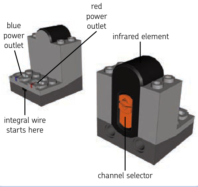
Figure 13-8: A front and back view of the Power Functions receiver
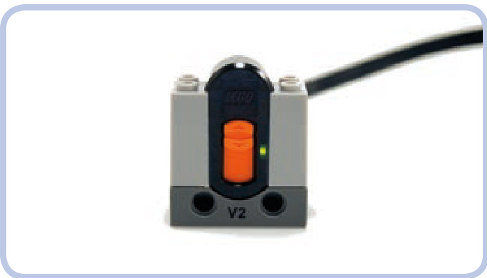
Figure 13-9: The V2 Power Functions receiver. Note the shining indicator LED.
remotes
As shown in Figure 13-10, there are two types of Power Functions remotes: a basic remote and a less common speed control remote. They work in a slightly different ways:
basic remote The go command makes motors run until the go command is no longer received. speed control remote The go command makes motors run until the stop command is received.
The key difference is that when the basic remote stops sending the go command, the motors stop. This means that we must maintain an infrared link between remote and receiver as long as we want the motors to go. Note that while moving the remote’s lever to the stop position stops motors immediately, breaking the infrared link means losing control over motors. With the link broken, they carry on the last received command for 2 seconds and then stop—unless we manage to reestablish the link during these 2 seconds.
With a speed control remote, we just have to send the go command to start motors and the stop command to stop them. There is no need to maintain a constant infrared link between sending these two commands.
Another difference is in how the remotes send commands. The basic remote keeps sending a command continuously for as long as you keep its lever in forward or reverse position. The speed control remote sends a command just once for every turn of a dial and once for pressing the stop button.
Not e It’s not recommended to use both types of remotes with the same receiver simultaneously. They will interfere with each other, causing all motors connected to the receiver to stop or to behave erratically.
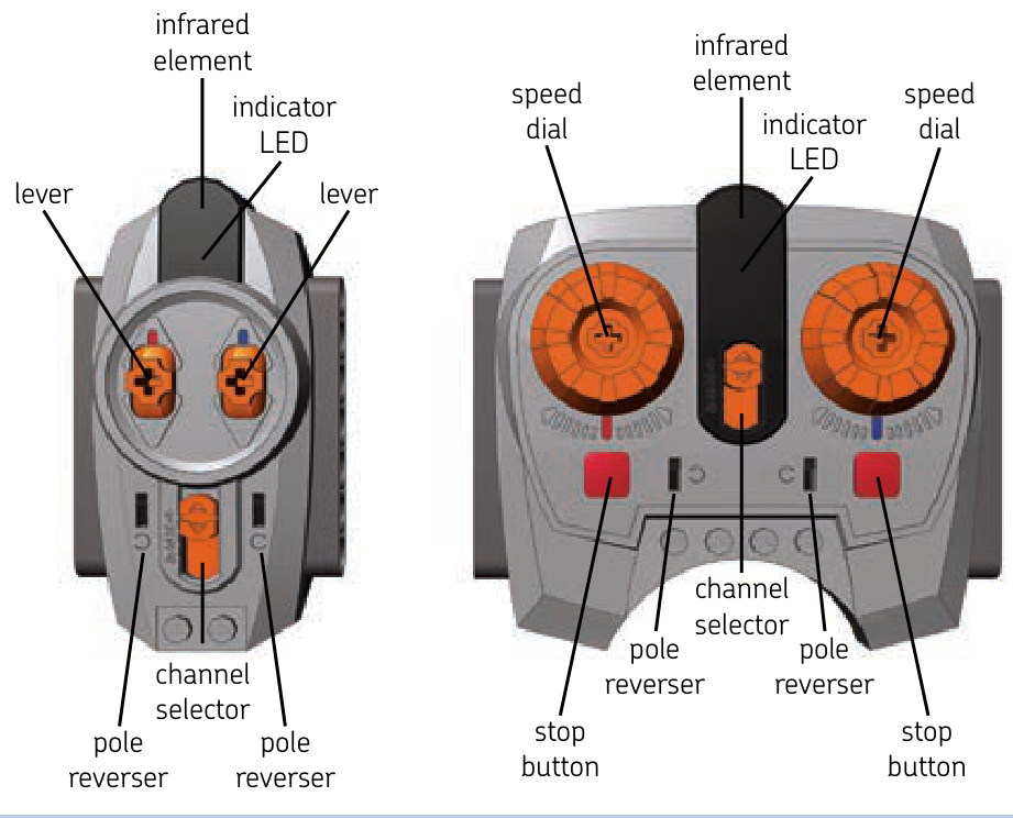
Figure 13-10: The Power Functions remotes: basic (left) and speed control (right). Each is powered by three AAA batteries.
This limitation becomes complicated when we want to drive and steer a model with a speed control remote, which is well suited for controlling drive but ill suited for controlling steering (unless you’re using the Power Functions Servo motor, as explained in “Understanding the Speed Control Feature”). The best solution, then, is to control steering with the basic remote on another channel by connecting the steering and driving motors to two separate receivers set to two different channels. The steering can be controlled by one receiver set to channel 1, and the drive can be controlled by a second receiver set to channel 2. There will be no interference as long as the remotes are set on proper channels.
basic remote
The basic remote comes with two levers: red and blue, each with forward, stop, and reverse positions. The levers return to the stop position when released. The basic remote also has two pole reversers, one for each lever. The remote is studs and has a channel selector and an indicator LED that shines green for as long as a command is being sent. The remote is powered by three AAA batteries inserted by unscrewing a cover on its bottom. Both its sides have seven pin holes each, allowing you to connect several remotes side to side with pins.
speed control remote
The speed control remote comes with two dials: red and blue. The dials have no definite positions and stay in place when released. This remote, too, has two pole reversers (one for each dial), two red stop buttons (one for each dial), a channel selector, and an indicator LED that blinks green when a command is sent. The remote is studs and powered by three AAA batteries inserted by unscrewing a cover on its bottom. Both its sides have seven pin holes each, allowing you to connect several remotes side to side with pins.
Note that this remote works in a special way with the Power Functions Servo motor: Instead of controlling the motor’s speed, the speed control remote controls the angle of its output. So rotating the dial 30 degrees right makes the Servo motor’s output rotate 30 degrees right, too—or left, depending on how you set the remote’s pole reverser.
understanding the speed control feature
There are 15 possible speeds in the Power Functions system: 7 forward, 7 reverse, and 1 “zero” speed, which stops the motors. Speed control is carried out by changing the voltage, meaning that speed control can affect not only a motor’s speed but also the brightness of the lights.
The basic Power Functions remote uses only three speeds: top speed forward, zero speed, and top speed reverse. The speed control Power Functions remote, on the other hand, comes with dials that can be rotated in one direction or another. Rotating a dial in one direction sends a speed command; rotating it in another sends a speed -1 command, but the rotation has to stop for a moment for the remote to finish sending the command. This means that the dials’ rotation is intermittent, not continuous.
You can rotate a dial through all speeds, from to but note that dials don’t stop even when maximum speed is reached. Since dials have no definite positions and can rotate infinitely, sending one command after another, it’s impossible to change speed very quickly or to tell the current speed from the dials’ position. This is why the speed control remote comes with separate stop buttons, one for each dial. While it’s possible to rotate a dial to stop a vehicle, it takes some time and precision; you have to watch the vehicle itself to know when you’re changing the speed to zero, for example, and not to . The stop buttons are the quick and sure way to go—you’ll see why when your model is heading fast toward the edge of a cliff!
Note that the rechargeable Power Functions battery has a dial that does have definite speed positions. This control affects all motors and lights connected to the battery directly or through a switch but not through a receiver, as the receiver ignores the battery’s dial.
modifying the remotes
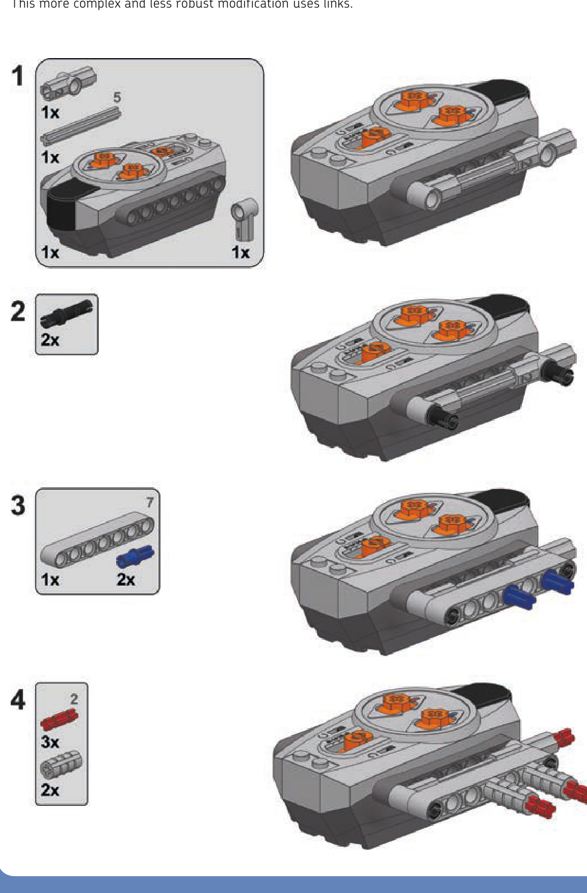
Many possible modifications can make the remotes better suited for our needs. Let’s look at three of them.
a basic remote with steering wheel
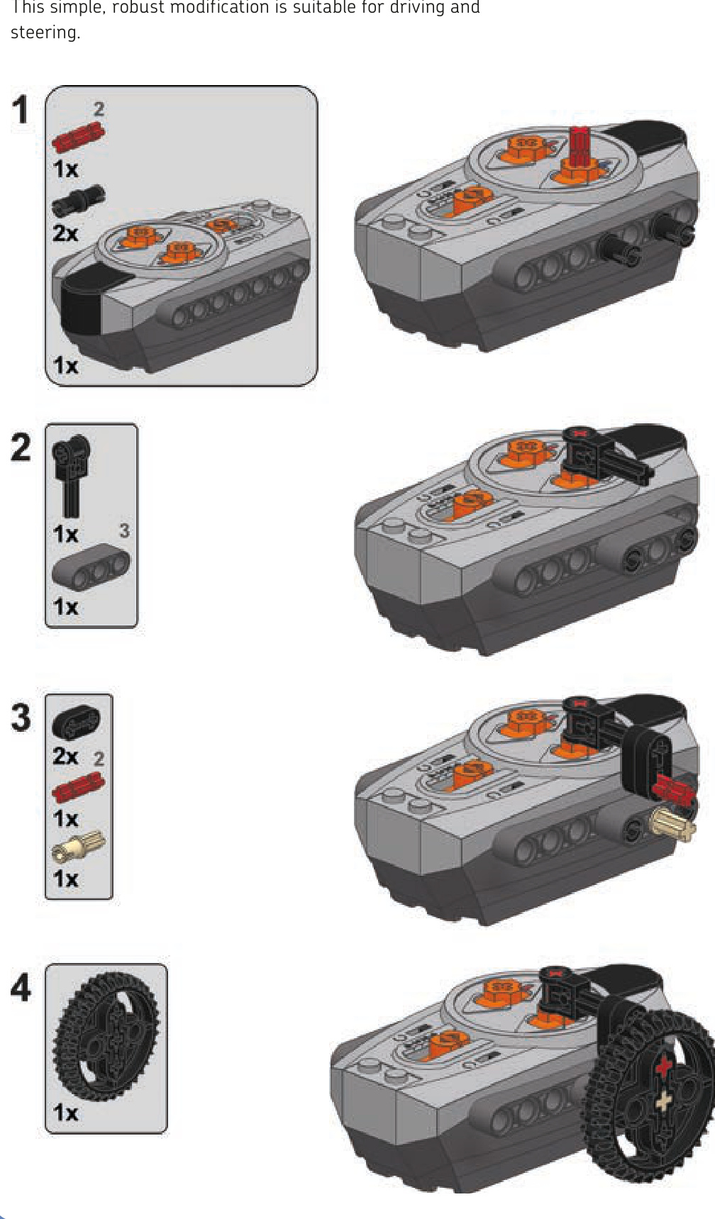
a basic remote with sideways lever
This more complex and less robust modification uses links.
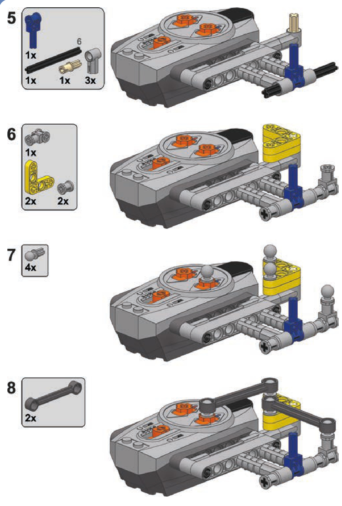
a speed control remote with central steering wheel
This modification is designed to control tracked vehicles, with each speed dial controlling a single track. Two speed dials are connected by a central steering wheel, which can be rotated as well as tilted forward and backward. With properly switched pole reversers, the steering wheel tilt controls drive, and the steering wheel rotation controls steering. To make the vehicle drive forward and then turn right, for instance, you would tilt the steering wheel forward and then rotate it right.
Note that this modification is subject to the disadvantages of the speed control remote—that is, it is limited to sending no more than two commands per second. It works best when operated carefully and not too fast.
linear actuators
large linear actuator
Linear actuators, designed as supplementary parts of the Power Functions system, are an interesting alternative to the LEGO pneumatics. They come in two variants, large and small, and both work thanks to inner screws. Each actuator has an input whose rotation makes the actuator extend or retract, depending on direction. When an actuator is extended or retracted to maximum, its inner clutch engages, allowing the input to continue rotating without damaging the actuator.
The actuators can thus be motorized without external clutches, and their inner gear ratio makes them work well with Power Functions motors without the need for external gearing. Their performance differs from that of LEGO pneumatics, so they can replace LEGO pneumatics in some applications and complement them in others. Let’s have a look at linear actuators and then compare them to pneumatics.
A large linear actuator is 11 studs long when fully retracted and 16 studs long when fully extended. It has a diameter of 2 studs, and it comes with two types of brackets (shown in Figure 13-11) that increase the diameter to 3 studs. One bracket provides an articulated mounting for the actuator, and the other provides a fixed one. It takes one or two 2L axles to firmly attach a bracket to the actuator. Examples of driving an actuator are shown in Figures 13-12 and 13-13.
Figure 13-11: A large linear actuator plus bracket with articulated (left) and fixed (right) mounting
Figure 13-12: Three examples of transferring drive to the small linear actuator. Note that all three have a 1:1 gear ratio.
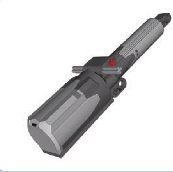
Figure 13-13: The bracket with fixed mounting can connect a motor and actuator as a single unit that can pivot around one of the mounting axles (light grey).
In 2010, LEGO announced that the actuators released earlier had a design flaw that could result in high friction occurring inside them when under load and lead to slow and coarse operation. The new design was introduced in September 2010. Actuators produced after this date are externally identical to the older ones, so the easiest way to distinguish them is by checking the production code on each actuator, shown in Figures 13-14 and 13-15.
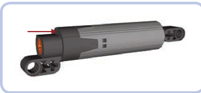
Figure 13-14: The location of the production code on the actuator is shown by the red arrow. Look for three digits and the letter X minted on the flat dark grey surface.
The production code consists of three digits and the letter X—for example, 36X0. The first two digits mark the week of the actuator’s year of production, and the last digit is the ending digit of the year of production. So the
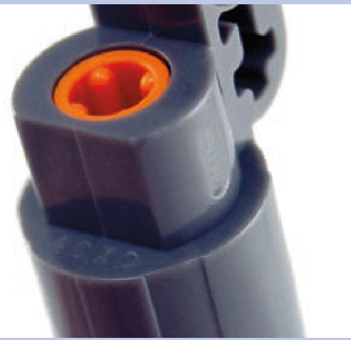
Figure 13-15: A close-up view of a linear actuator. The production code is 40X0, which means the 40th week of 2010, or four weeks after the improved design was introduced.
production code means the 36th week of 2010; this is exactly when the new design was introduced. Actuators produced before this date—for example, 29X0—are of earlier design; actuators produced after this date—for example, —are of improved design. Keep in mind that even if you have “flawed” actuators, it doesn’t necessarily mean that failure will occur.
The large linear actuators can handle impressive loads. Their disadvantage, however, is their inner clutch, which creates significant noise and vibrations when engaged.
small linear actuator
A small linear actuator is 7 studs long when fully retracted and 10 studs long when fully extended. It has a diameter of a single stud and a fixed bracket that is 3 studs wide.
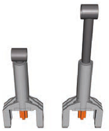
Figure 13-16: Three examples of transferring drive to the small linear actuator. Note that all three have a 1:1 gear ratio.
Instead of an axle hole, it has input in the form of a 1L axle. Figure 13-16 shows simple ways of driving a small linear actuator.
The load capacity of the small linear actuator is much smaller than that of its larger variant but still impressively useful given its size. Unlike the large actuator, the small one comes with a plastic internal shaft, which is less robust than the large actuator’s metal one. The clutch in the small linear actuator works very smoothly and engages almost seamlessly. The small actuator can be very space efficient when combined with the Medium motor.
linear actuators vs. pneumatics
Linear actuators can do most of the tasks that pneumatic cylinders can, but they were not designed to replace them. The two systems differ in many areas, and the best results can be achieved by combining them so that they complement each other’s advantages. Here’s what linear actuators look like when compared to pneumatics.
Advantages:
Have a higher load capacity
Can be motorized directly, without the need for compressors or valves
Maintain better accuracy in all positions, as they don’t depend on air pressure
Maintain their position under any load; their inner screws lock them once stopped so they can’t be moved by the weight of the load
Don’t have pneumatic hoses, just driveshafts
Disadvantages:
Can be difficult to transfer drive to, as driveshafts are less versatile than pneumatic hoses; this disadvantage grows with more complex systems and with the number of actuators
N Move with constant speed, lacking the smoothness of movements that can be achieved with pressure-dependent pneumatics
Are generally larger in size
N Large actuators can cause problems when their inner clutches engage, as they produce lots of vibrations
N Are much more difficult to pair
N Resemble real-life hydraulic systems significantly less than pneumatics do
extension wires
We already know that the vast majority of the Power Functions electric components come with integral wires that are permanently attached to them on one end and have a plug on the other. These wires are obviously limited in length, which is why two kinds of extension wires were introduced: a wire and wire (see Figure 13-17).
Beyond the obvious goal of adding extra length to any PF electrical connection, the extension wires have one very important feature: Each comes with one adapter plug. An adapter plug is a special variant of the Power Functions plug that can have regular PF plugs attached on top of it and old 9V system plugs attached to the bottom of it (see Figures 13-18 and 13-19). This way, each extension wire allows you to connect elements of the Power Functions and old 9V systems together.
A variety of 9V elements can be controlled with the Power Functions system, including all motors (the speed control feature works with them as well) and all types of lights. It is also possible to integrate PF elements into the 9V system to a limited degree. For example, the PF motors can be controlled with 9V battery boxes and switches, but PF receivers work only with PF power supplies.
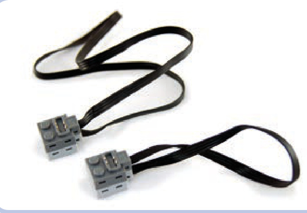
Figure 13-17: Power Functions extension wires: 50 cm long (top) and 20 cm long (bottom)
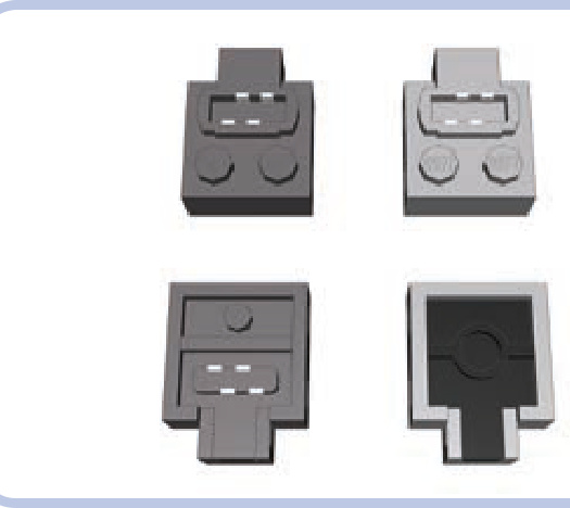
Figure 13-18: Top and bottom view of a regular Power Functions plug (left) and the adapter plug (right). Each extension wire comes with one plug of each type.
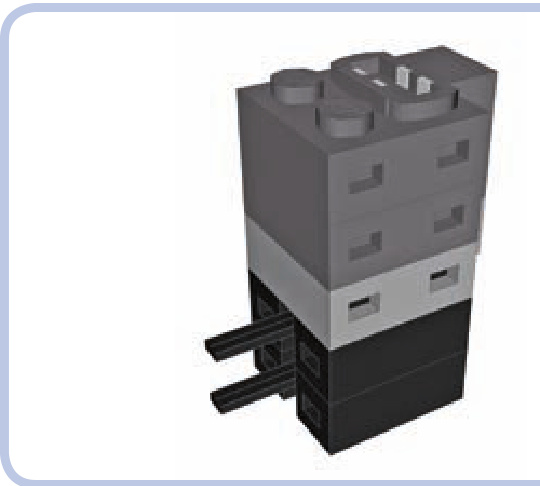
Figure 13-19: The Power Functions adapter plug (light grey) can have an unlimited number of Power Functions plugs (dark grey) attached on top of it and an unlimited number of 9V plugs (black) attached to its bottom.
power functions elements as LEGO sets
The following Power Functions elements have been released as separate LEGO sets:
8869: switch
8870: LED lights
N 8871: extension wire, long
N 8878: rechargeable battery
N 8879: speed control remote
N 8881: AA battery box
8882: XL motor
8883: Medium motor
8884: receiver
: basic remote
: extension wire, short
: rechargeable battery transformer
: AAA battery box
miscellaneous elements
There are just a few more elements of the Power Functions system, and most of them are highly specialized—for example, train sets—so we will omit them here. That leaves just two elements so universal that they deserve to be described.
switch
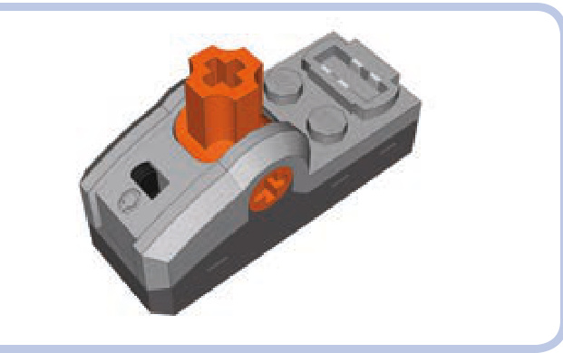
As mentioned earlier, the switch is the simplest control element. It is studs and has a 1-brick-tall base, and it comes with an integral wire, one power outlet, one pole reverser, and an orange lever. The lever is identical to the one on the basic remote, with three positions—forward, stop, and backward—except that it doesn’t return to the central position. It also has an axle hole through which any axle can be put—this comes in handy, for example, when we want to motorize the switch.
LED lights
The PF system’s lights, shown in Figures 13-20 to 13-22, are a pair of LEDs with a piece of wire and a regular Power Functions plug. At half of its length, the wire enters a black brick that separates in two, so the two LEDs can be placed relatively far from each other. Note that the black brick is not a plug of any kind: It’s fully closed, just like a standard LEGO brick. The LEDs are enclosed in transparent housings that are less than 2 studs tall and less than 1 stud wide and that have protruding tubes with LEDs inside that fit perfectly into a pin hole.
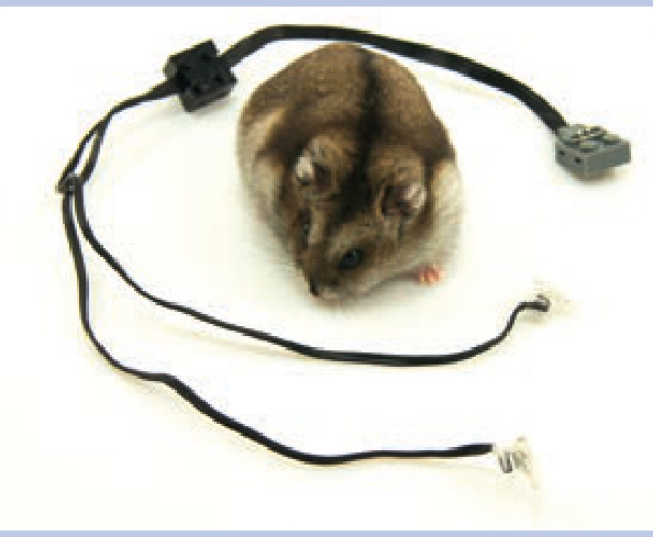
Figure 13-20: The Power Functions LEDs with a hamster provided for scale
Figure 13-21: Side view of the LEGO LED. You can see part of the wire tucked in to prevent it from being ripped off. The actual LED is located in a protruding tube that fits into a pin hole and is slightly less than a single stud long.
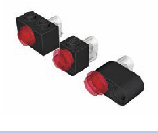
Figure 13-22: The most common examples of installing LEDs in other LEGO pieces. The LEDs fit perfectly into a pin hole. Since their protruding part is less than a stud long, there is still enough room to put in, for example, semitransparent round plates from the other side, creating lights in various colors.
The LEDs provide bright white light, directed only forward. Their power consumption is minimal, and their brightness can be controlled with the Power Functions speed control feature. Note that the type of LEDs used by LEGO has changed over time: The glow of older batches is slightly yellowish, while the glow of newer batches is bluish.
part IV
advanced mechanics

14
wheeled steering systems
The steering of wheeled vehicles is a complex subject in automobile design. While some real-life issues are of lesser importance in LEGO models because of their limited size and weight, it still pays to understand the principles at play.
In this chapter, we’re going to learn how to build typical LEGO steering systems as well as how to implement optional features, such as return-to-center steering. We’ll also explore issues of steering geometry and multi-axle steering.
Note that this chapter omits vehicles with fewer than four wheels. Steering bikes or trikes is elementary, so we are moving straight to where the real challenges begin.
basic LEGO steering systems
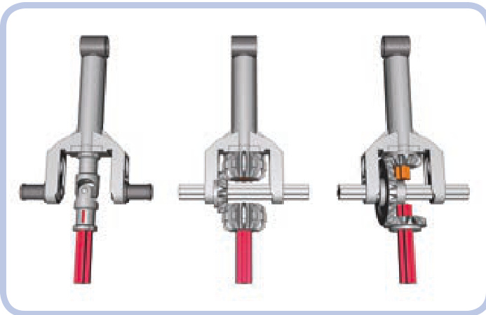
The steering systems in LEGO constructions can be built with a number of specialized pieces, but it’s also perfectly possible to rely only on common pieces. Let’s start our exploration of steering by examining a typical steering mechanism, shown in Figure 14-1.
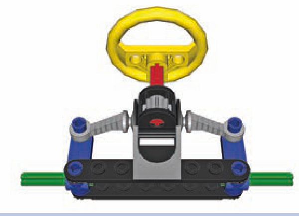
Figure 14-1: A typical LEGO steering mechanism
Note that we will be using colors consistently throughout this chapter: The black pieces are parts of the chassis, and the yellow one is obviously a steering wheel. That leaves four other important parts:
a steering shaft (red) This is an axle that connects a steering wheel or a motor to the pinion of the rack-andpinion gearset.
a rack-and-pinion gearset (grey) This gearset consists of a pinion (here, an 8-tooth gear) and a rack, which is a toothed plate, below it (see Figure 14-4); when the pinion rotates left or right, it makes the rack slide.
steering arms (blue) These arms rotate around the connection to the chassis, and their rotation is controlled by the rack.
spindles (green) These are the axles in the steering arms on which the wheels are mounted.
Figure 14-2 shows our mechanism in action. Rotating the steering arms makes the entire vehicle turn. And obviously, to turn, the vehicle needs at least one more axle, as Figure 14-3 shows.
In Figure 14-2, the rack gear is a specialized piece (#2791) that is slightly elastic, allowing it to bend to stay mated with the round pinion gear as the steering wheel turns. The pinion gear can be used with other gears, but we’d have to compensate for the rotation of the steering arms. Figure 14-4 illustrates the problem.
When the steering arms are turned, the pins that connect them to the rack actually trace part of a circle. This causes the rack to move in two dimensions: not only left and right but also forward and backward. Only the lateral movement is desired, as the forward-and-backward displacement can disengage the rack from the pinion. Figure 14-5 shows the simplest solution to the problem: adding an extra pinion.
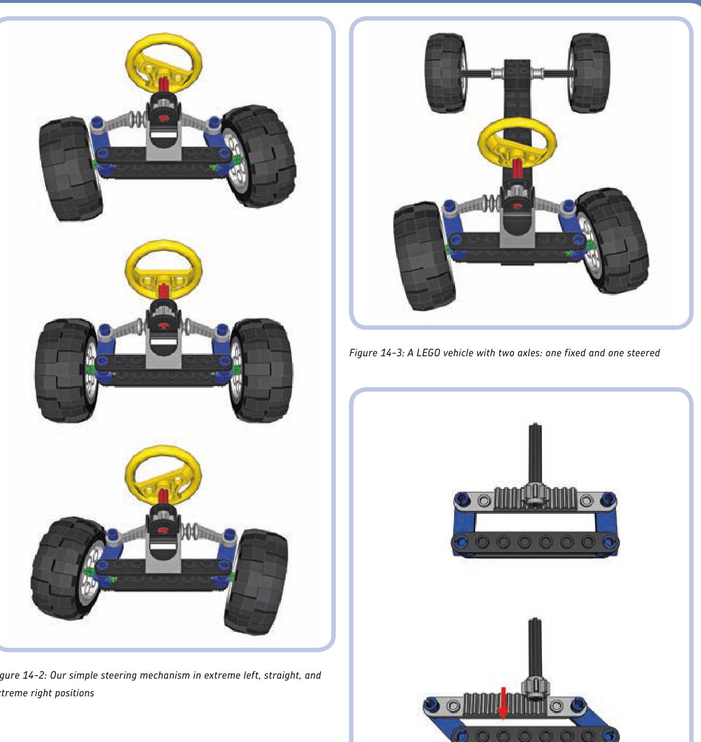
Figure 14-4: The rotation of the steering arms (blue) makes the rack (light grey) move not only side to side but also forward and backward.
Another solution is to place the pinion in the middle of the rack’s path of forward-and-backward motion, as shown in Figures 14-6 and 14-7.
These figures also introduce a new, simple element of the steering system. When we use nonspecialized pieces to build a steering system, we’ll use two pieces: a rack gear (shown in light grey under the pinion), which is a -stud plate with teeth on top of it, and a tie rod (shown in light blue). A tie rod connects the ends of the steering arms to the rack gear.
As you can see, the tie rod travels forward and backward, requiring a margin of free space—the 2-stud-wide gap around it. But we may not want to waste space for such a gap; another solution is to make the rod more complex, as shown in Figure 14-8.
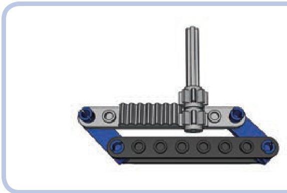
Figure 14-5: The simplest solution to the problem of an “escaping” rack is using two pinions so that when the rack moves away from one, it will be meshed with the other.
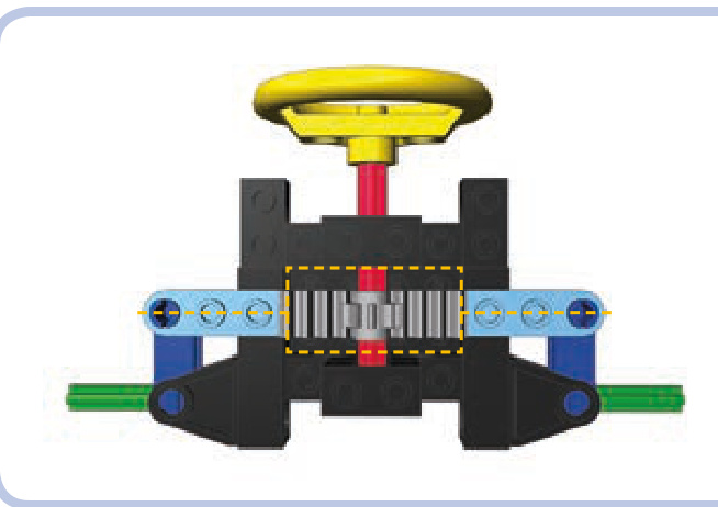
Figure 14-6: A steering mechanism in straight position. Note that the light blue tie rod is located in the center of the 2-stud-wide gap around the pinion
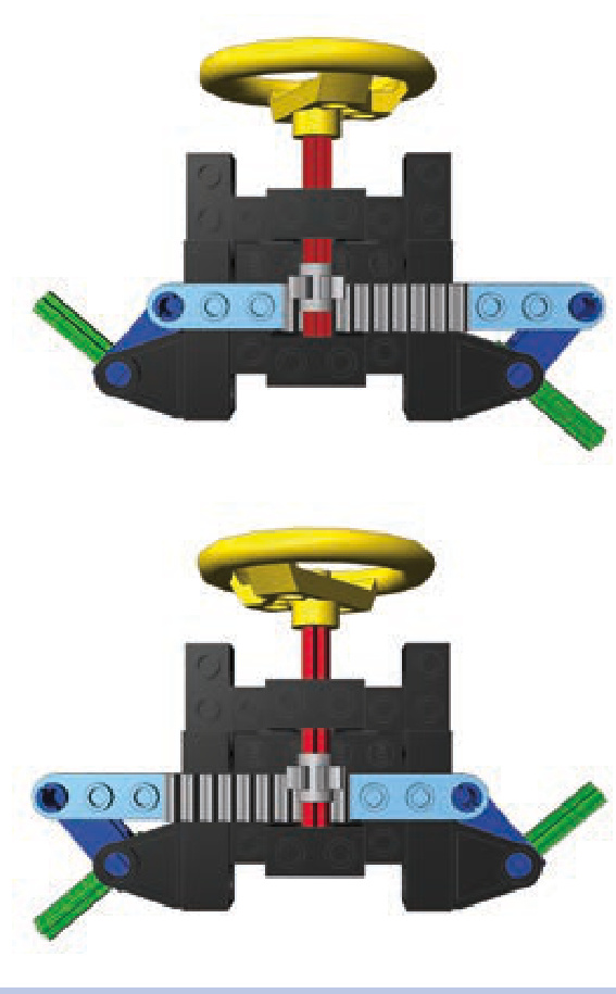
Figure 14-7: A steering mechanism in extreme right and extreme left positions. Note that the tie rod moves forward inside the 2-stud-wide gap around the pinion.
Figure 14-8: A steering mechanism with a three-piece tie rod. The short, articulated sections on the sides pivot to accommodate the rotation of the steering arms.
Here the tie rod consists of three sections: a long central one (with the rack) and two short ones on its sides, connected by pins. These short sections pivot to accommodate the rotation of the steering arms and reduce the central section’s forward-and-backward travel to zero, as Figure 14-9 shows.
The three-piece tie rod is a reliable and popular solution, but its side sections must be shorter than the central one. The whole assembly is rather wide and thus not suited for narrow vehicles. We can solve this by building a very simple steering system in which the rack gear is replaced by a lever, as Figure 14-10 shows.
You now know three solutions to the problem of a tie rod’s travel, and you have seen examples of simple steering systems built with a handful of common pieces. Now that your steering system is working, you may want to add features to it.
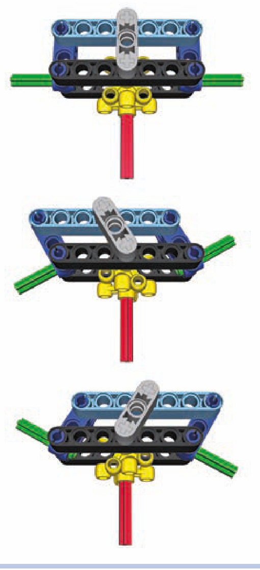
Figure 14-9: A steering mechanism with a three-piece tie rod in extreme left and right positions. Note that the longitudinal travel of the central section is zero.
Figure 14-10: A steering mechanism without a rack. Instead, it uses two knob wheels and a short lever (grey) to transfer movement from the steering shaft to the tie rod.
return-to-center steering
Return-to-center steering is just what the name implies: a mechanism that returns the steering system to the cen ter (straight) position when the system is released. Such a mechanism is best placed between the steering system and a motor controlling it, and such a “self-centering” design complements the use of remote controls. It allows you to build a steering system that steers to extreme left or extreme right when you push levers on your remote and that returns to center when you release it.
Not e These mechanisms use the basic Power Functions remote and a regular motor. You can use the speed control PF remote and PF Servo motor instead, which together provide not only a return-to-center system but also proportional steering. See Chapter 13 for details.
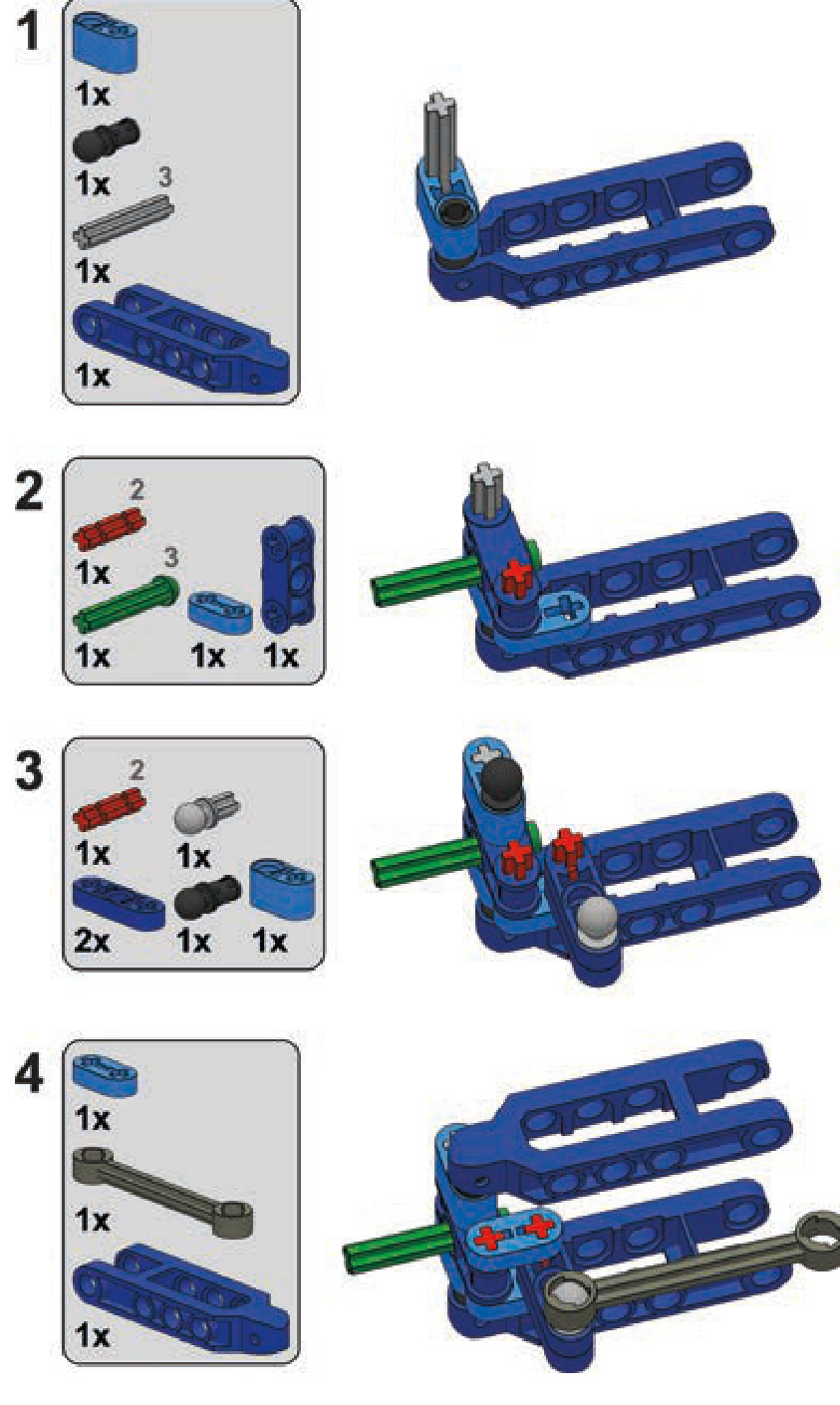
The easiest way to build a self-centering steering system with LEGO pieces is to use a rare specialized piece, # , often called a hockey spring. It comes with a spring inside and can be attached to a PF Medium motor (as shown in Figure 14-11). In such a configuration, it will backdrive the motor to the central position every time the motor stops.
If you cannot find this specialized piece, you can use a rubber band for a simple centering mechanism. Shown in Figure 14-12, the mechanism consists of the band (white), which squeezes two beams (yellow) together to the sides of a connector sitting on the steering shaft (red). As the motor starts to rotate the shaft, the connector pushes the beams apart. If the rubber band is strained enough, it will stop the connector quickly, and when the motor stops, it will squeeze the beams back together, returning the connector and the shaft to the central position. Note that you have to find a rubber band providing just the right tension for this mechanism to operate smoothly.
As with any mechanism, return-to-center steering has its pros and cons. It works fast and simplifies the control of a model, but it doesn’t allow accurate maneuvering because it only has three possible positions. This makes it better suited for fast models where a steering system has to react quickly, rather than for slower ones that benefit from a steering system that allows for greater accuracy. It’s also risky to use return-to-center steering with a large steering lock because rapid wide turns can make a vehicle unstable. (Steering lock is the maximum angle that wheels on a steered axle can be turned, as described in Chapter 1.) In my experience, any model that isn’t built specifically for speeding will be better off with a regular steering system that allows you to adjust the driving direction accurately. In most cases, the PF Medium motor geared down to a 9:1 gear ratio provides optimum speed/accuracy balance for a regular steering system.
Ackermann steering geometry
When a wheeled vehicle makes a turn, its inner and outer wheels follow circles of different radii because the width of the vehicle separates them. If the inner wheels follow a circle of radius , then the outer wheels follow a circle of radius (equal to plus the width of the vehicle), as Figure 14-13 shows.
A regular steered axle turns both left and right wheels at exactly the same angle, which means that none of the wheels follows exactly its proper radius. This creates additional friction and tire wear. Ackermann steering geometry corrects that by turning wheels at different angles. More specifically, it turns them so that they are perpendicular to the center of the vehicle’s turning radius, as shown in Figure 14-14.
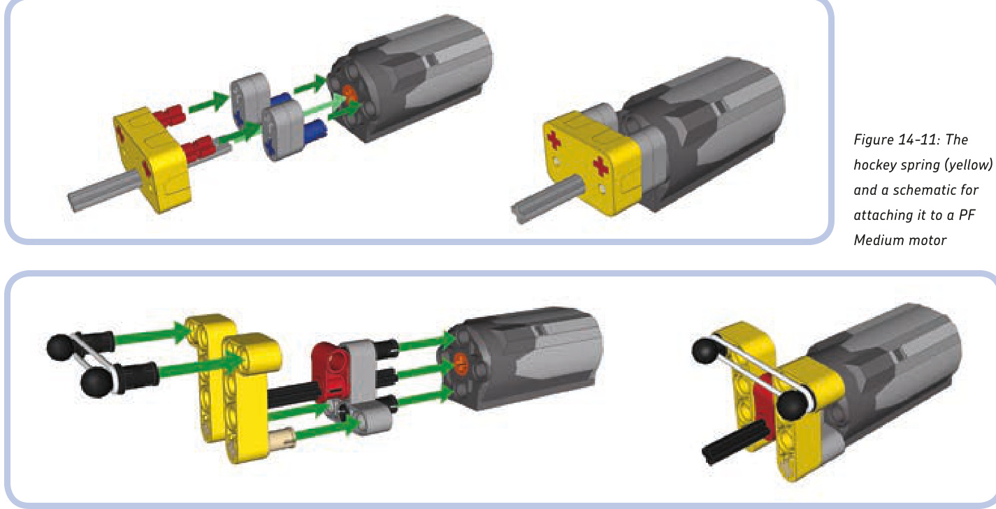
Figure 14-12: The rubber band–based return-to-center steering attachment for a PF Medium motor
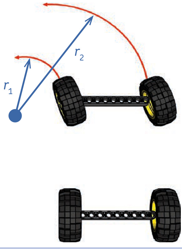
Figure 14-13: The inner and outer wheels of a steered vehicle follow circles of different radii: is equal to plus the width of the vehicle.
This geometry, which makes the wheels follow correct radii, is achieved by modifying the steering arms so that they point at the middle of the rear axle, as Figure 14-15 shows.
When it comes to LEGO vehicles, this additional friction and the tire wear are negligible, except for very heavy and large models. The improved handling that comes with Ackermann geometry is advantageous but only noticeable with large vehicles with significant steering lock. Ackermann geometry is important enough to be used in many high-end RC cars, and two official LEGO Technic supercars use it: the 8865 and 8880 sets (shown in Figure 14-16). Both use independent steered suspension, which is also driven in the 8880 set.
Both the 8865 and 8880 sets use special steering arms with shifted pivot points, shown in Figure 14-17. Both are rare pieces by now, but we can build our own custom steering arm using other pieces, as shown in the building instructions on page 198.
There is one more way to achieve Ackermann geometry: We can use a three-piece tie rod with a longer central section and with the two side sections set at an angle, as shown in Figure 14-18. Such a tie rod has little travel, and it should be placed in front of the front axle. Note that with this solution, the steering arms don’t point at the middle of the rear axle, so it’s difficult to see whether the proper geometry is achieved. This solution puts very high forces in the tie rods. Note that the central gear rack needs to be guided to keep it perpendicular to the chassis.
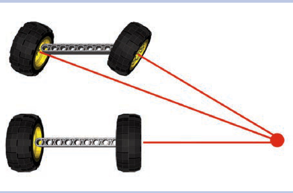
Figure 14-14: Ackermann steering geometry keeps the wheels on the steered axle perpendicular to the center of the turning radius when making a turn.
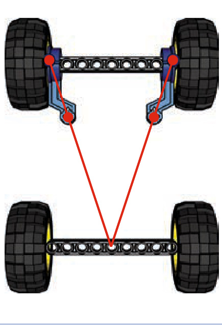
Figure 14-15: A proper Ackermann geometry: The front axle’s steering arms point at the center of the rear axle.
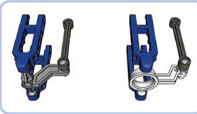
Figure 14-17: Steering arms from the 8865 (left) and 8880 (right) sets, mounted in suspension arms (blue). Both have shifted pivot points to allow Ackermann geometry; the 8880 arm also allows the wheels to be driven.

Figure 14-18: Ackermann steering geometry achieved by using a three-piece tie rod with a longer central section
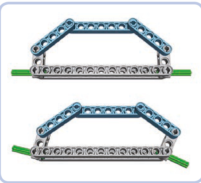
Figure 14-16: The LEGO 8865 and 8880 sets are designed with Ackermann geometry in mind.
Ackermann steering geometry was included in the official LEGO sets as an additional technical highlight rather than for its actual advantages. Given the weights and sizes of most LEGO models, the benefits of such a sophisticated solution are negligible. Still, many builders consider including it in a model a great display of skill.
a simple steering arm with Ackermann geometry
convergence of axles
While discussing Ackermann steering geometry, we learned that every vehicle has its center of turning radius. When the wheels are turned, the center is where lines perpendicular to each wheel meet (ignore the outer steered wheels if you use a regular steering geometry), as shown in Figures 14-19 and 14-20. The center can be closer or farther from the vehicle, depending on how much the wheels are turned.
Now, consider a line that points at the center and at the same time is perpendicular to the chassis of the vehicle. In Figure 14-21, that line goes exactly through the rear, fixed axle. No matter how much the steered wheels are turned, this line will always cross the chassis in the same place. We call it the convergence line.
When the axles of a vehicle are convergent, the vehicle turns easily and with little friction. The exact placement of the convergence line depends on the nonsteered axles. For example, when there is one such axle, the convergence line agrees with it; when there are two such axles, the convergence line is exactly between them (as shown in Figure 14-22). When there are three such axles at equal intervals, the convergence line agrees with the middle one, and so on.
When we have more than one steered axle, the convergence line helps to determine the proper spacing between them and the difference in their steering locks. For example, if we have steered axles in the front and rear of the vehicle, they should be symmetrical to the convergence line, which means that the front axle should steer in the opposite direction of the rear axle, as shown in Figure 14-23.
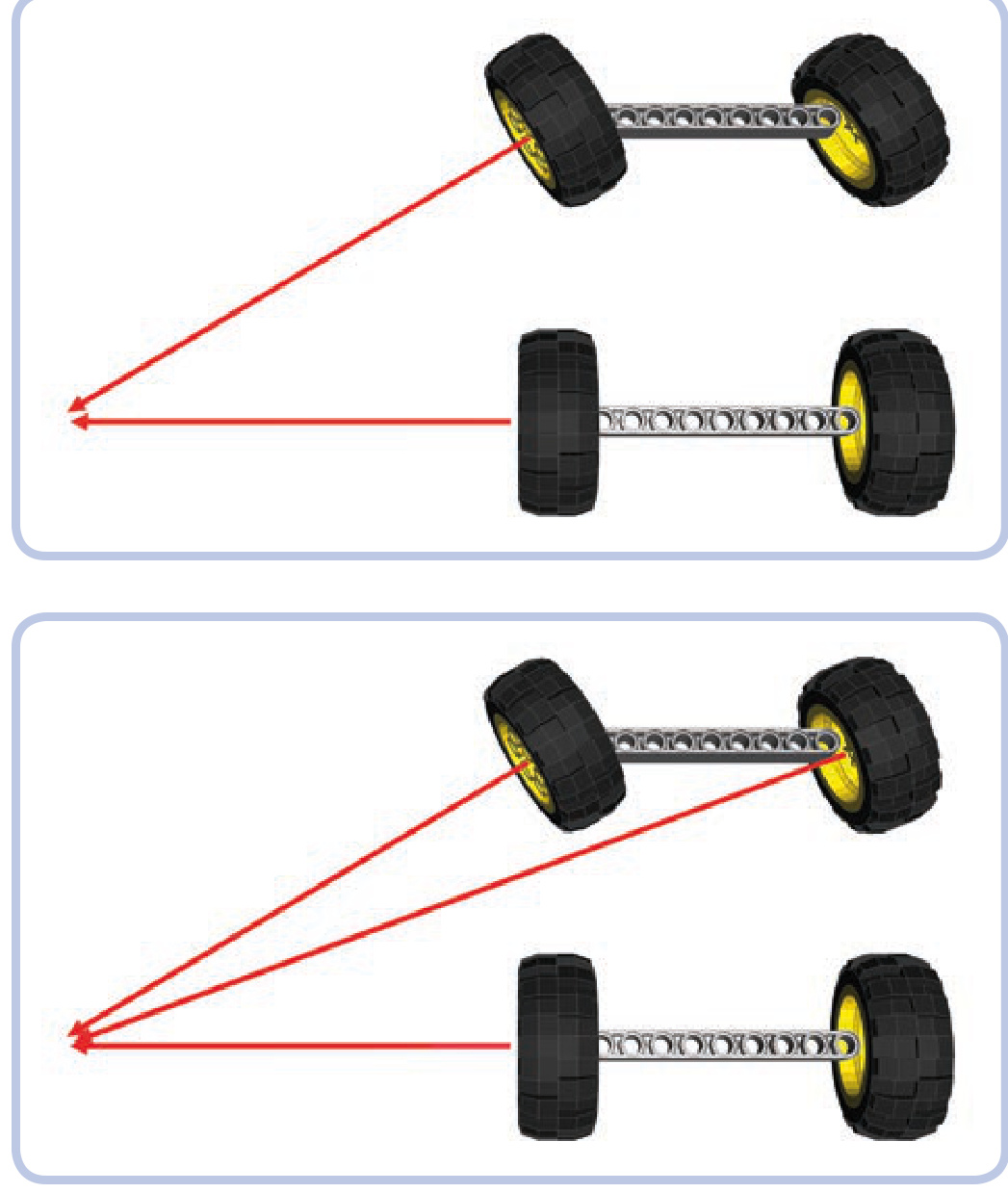
Figure 14-19: The center of turning for a vehicle with regular steering geometry: The outer steered wheel is ignored.
Figure 14-20: The center of turning for a vehicle with Ackermann steering geometry: All wheels “point” at it.
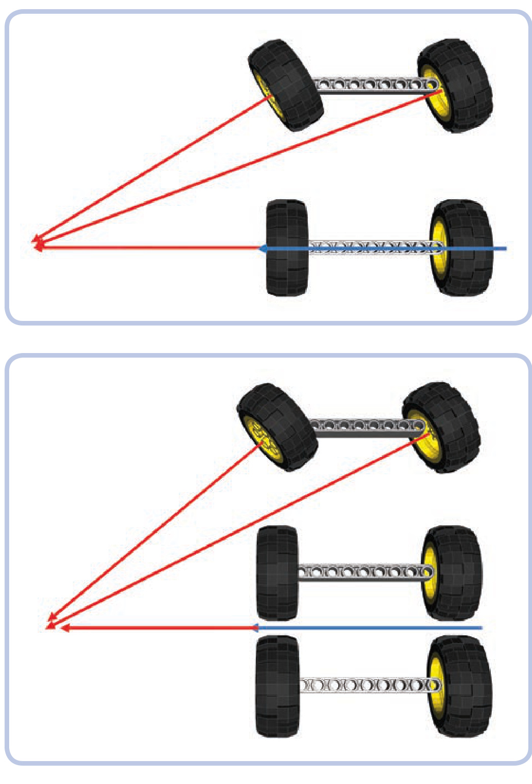
Figure 14-21: Blue marks the convergence line—the line that is perpendicular to the chassis while pointing at the center of turning.
Figure 14-22: For a chassis with a single steered axle and two rear nonsteered ones, the convergence line lies exactly between the rear axles. In this example, since the rear wheels do not point at the rotation center, they will scrub in a turn. This is a big problem for vehicles and trailers with many nonsteered axles. It’s also a big problem for airplanes, which turn very tightly.
Figure 14-24 shows a chassis with two steered axles and one nonsteered axle. We know that in this case the convergence line agrees with the only nonsteered axle. We need to calculate the relationship between the angles of both steered axles, and to do this, we need to know these angles. This can be done by comparing distances between the steered axles and the convergence line for a given angle
The most complex case is when we have two or more steered axles next to one another; to maintain convergence, they need different steering locks. It is possible to calculate this difference, but it involves using trigonometry to calculate an inverse tangent.
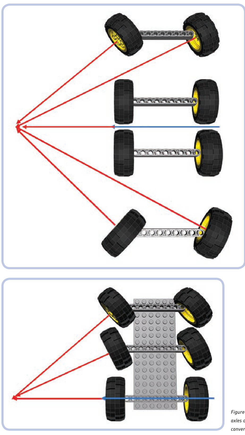
Figure 14-23: If there are steered axles in the front and rear, they should be symmetrical to the convergence line.
Figure 14-24: The steering locks of the two front axles of this chassis should differ to maintain convergence.
of the front wheels. In this example, let’s assume the angle is 45 degrees. As we can see, the front axle is 13 studs away and the middle one is 7 studs away from the convergence line. We need to calculate the relationship between the shorter and longer distances:
Next, we need to find the inverse tangent (arctangent) for this relationship.
We have just calculated the angle at which the middle axle should be steered, and we know that the angle of the front axle is 45 degrees. Now we need to compare these angles to know the difference between angles and translate it into gearing in the steering system.
We can round the result to 0.6. This means that the middle axle should steer at 0.6, or about 60 percent of the front axle’s angle. Therefore, the steering on the middle axle should be geared down to 0.6 as compared to the front axle. We can do this in two ways:
Use a single steering shaft for both axles but with pinions of different sizes on each rack (see Figure 14-25). N Use the same pinions on both axles but with two steering shafts with gearing between them (see Figure 14-26).
Figure 14-25: First method for two axles with different steering locks: a single steering shaft with two pinions of different size
Figure 14-26: Second method for two axles with different steering locks: two identical pinions but two separate steering shafts with gearing between them
Whichever way we choose, it all comes down to the gear sizes. If we use a 20-tooth gear on the front axle, here’s how we calculate the middle one:
As you see from the calculation, we need a 12-tooth gear. When assembling the model, we also need to make sure that the two steered axles are aligned.
Finally, a simple (and math-free!) alternative is to make a simple mock-up of the chassis showing just the distances between axles. You place the mock-up on a sheet of paper, turn the wheels so that they point at the center of the turning radius, and physically draw the lines and measure the angles. If you find any of these methods troublesome, you can always ignore convergence completely. It won’t stop your models from driving or turning—they just won’t handle as well as they would with convergent axles.
15
wheeled suspension systems
The previous chapter introduced us to the principles of steering in wheeled vehicles. Now, we’ll take a look at two topics that are inextricably linked to steering axles: suspending axles and driving them. These interrelated mechanisms are frequently “separate,” yet because they affect the same final element, the wheels, they can be built only in a limited number of combinations. For example, a suspension of a given type will work only with certain steering and drive systems.
Any axle of a wheeled vehicle can be suspended, driven, and steered at the same time. An axle can, of course, do none of these things and merely hold wheels together, but since such an axle is very simple to build, this chapter will focus on axles that are at least driven. We’re going to discuss axles in four groups of increasing complexity:
Driven axles (those that receive power) Driven and suspended axles Steered and suspended axles Driven, steered, and suspended axles
After going through the first group, we’ll focus on the concept of suspending wheels; we’ll learn how suspension systems work, how they are categorized, and how to choose the suspension that best suits our needs.
driven axles
A driven axle is a mechanism that connects two wheels while transferring drive to them from the chassis. The power is usually received from a driveshaft that is longitudinal to the chassis and perpendicular to the axle. Connecting these two elements is necessary, and a pair of bevel gears is the simplest solution. But in practice, bevel gears are prone to skipping under high torque, and a driven axle is where we can expect high torque. This leaves us with two other options: a differential or a pair of knobs. A differential is less likely to
skip, especially if braced inside a proper structure (shown in Figure 15-1), and knobs are extremely unlikely to skip at all thanks to their design (shown in Figure 15-2).
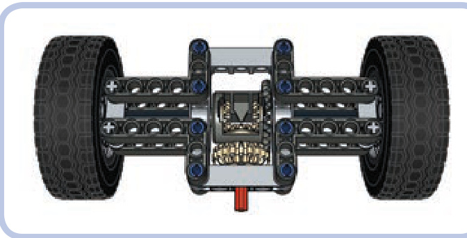
Figure 15-1: This is what a simple driven axle, also known as a live axle, can look like. The driveshaft (red) drives the 20-tooth double-bevel gear meshed with a differential case. The studless frame braces the differential and prevents it from skipping. Note that there are two separate 7-stud-long axles connecting the differential to the wheels—axles used in this way are called halfshafts.
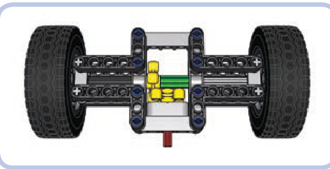
Figure 15-2: The same simple driven axle with a pair of knob wheels instead of a differential. The knob wheels are very unlikely to skip even if braced in a weak structure. Note that the two wheels’ axles are now connected with an axle joiner (green), so they work like a single axle. For more information about using differentials, their pros and cons, and even ways of creating a custom differential, see Chapter 8.
suspension systems: concept and categories
A suspension is a system of linkages that connects the chassis of the vehicle to the wheels. Its primary purpose is to keep all wheels in constant contact with the ground, thus ensuring stability and proper traction of the vehicle. The suspension can also isolate the chassis from bumps and vibrations generated by the ground—but this is actually its secondary function, and it’s not even present in all types of suspensions.
In order to maintain stability, a vehicle needs to be supported at no fewer than three points. For example, a bicycle is supported at just two points—where its wheels touch the ground—and it will fall over unless you support it at another point or drive it fast, in which case the stability comes from the gyroscopic effect of a wheel’s rotation. So a vehicle needs at least three points of support, and we’ll call these points fulcrums in our suspensions. Sometimes they are simply called points—hence the name 3-point suspension for a suspension that provides three fulcrums for a vehicle and 4-point suspension for one that provides four.
It’s important to understand that with a suspension system, the number of wheels and the number of fulcrums differ. An unsuspended axle provides two fulcrums (one at each wheel), while a suspended axle provides just one, at the point of its attachment to the vehicle. For instance, a vehicle with four wheels can have one suspended and one unsuspended axle to get three fulcrums (Figure 15-3). A six-wheeled vehicle will also have three fulcrums if all three axles are suspended (Figure 15-5).
Consider a few simple examples in Figures 15-3 to 15-7 of chassis with various numbers of wheels and three (or more) fulcrums (fulcrums are marked with red arrows, chassis are black, and oscillating suspension parts are blue).
The way the wheels move in relation to each other is the first way to categorize a suspension:
N A suspension is independent when one wheel on a given axle can move without affecting the other one. N A suspension is dependent when it’s impossible to move one wheel on a given axle without affecting the other one.
In dependent suspensions, when one wheel of the axle goes up, the other one goes down, and vice versa. All the simple examples here are dependent (Figures 15-3 to 15-7).
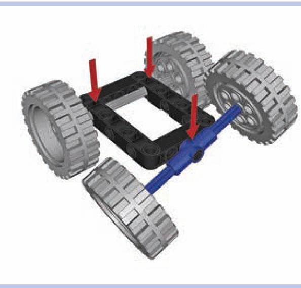
Figure 15-3: A simple chassis with four wheels, including two on a suspended axle
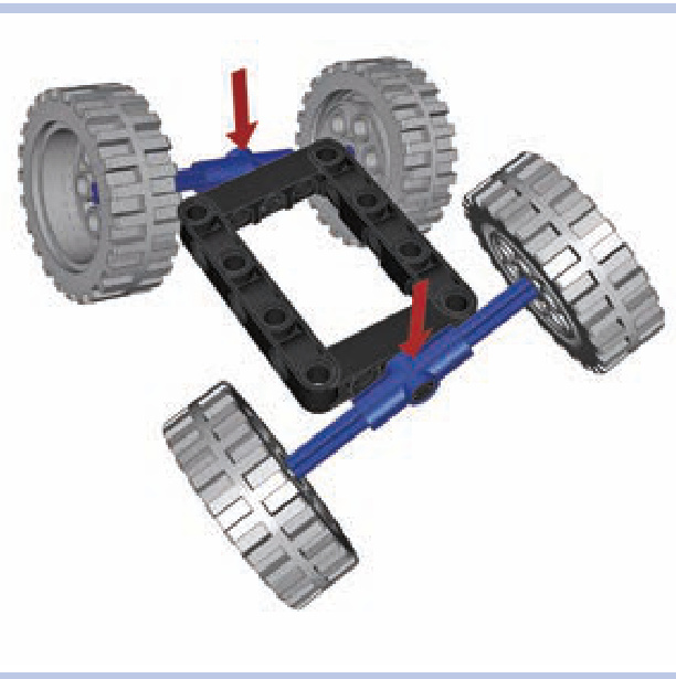
Figure 15-4: It’s possible to build chassis with just two fulcrums, like this one with two suspended axles, but the chassis will need elastic elements supporting it against the axles to prevent it from falling to the side.
Also note that suspension types can vary between different axles. One vehicle can have, for example, an independent front suspension (on the front axle) and a dependent rear suspension (on the rear axle). Such a combination is actually quite popular because it allows you to build vehicles that are only as complex as necessary. In many cases, there is simply no need to use advanced suspension systems on all axles.
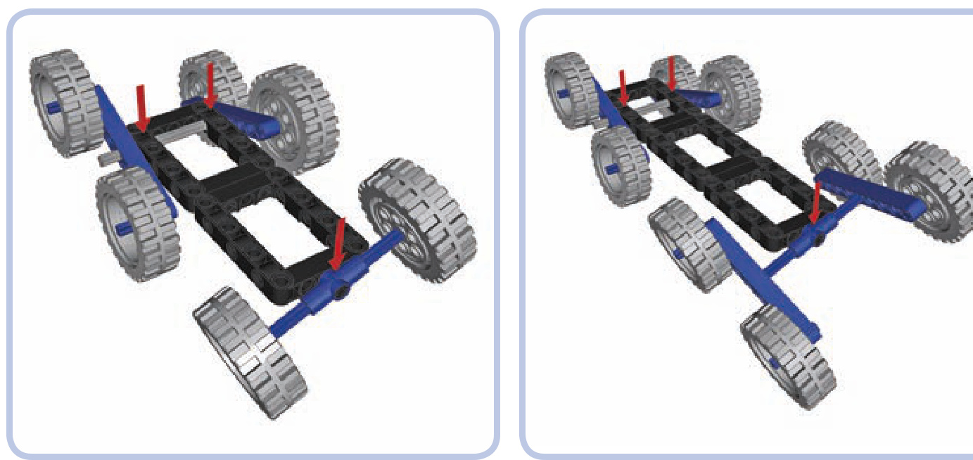
Figure 15-5: A chassis with six wheels, all suspended
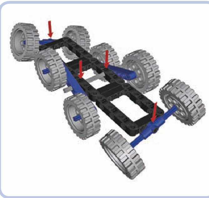
Figure 15-6: A chassis with eight wheels and four fulcrums, meaning it has a 4-point suspension. Long, multiwheeled vehicles often have more than three fulcrums.
Secondly, we can categorize suspensions by how they transfer shock from the road surface:
A suspension is sprung when the chassis is supported by elastic elements attached to the given axle so the shocks from the axle are partially absorbed.
Figure 15-7: Even with many wheels, the number of fulcrums can be reduced by using more complex suspension systems that oscillate around more than one axle. This allows the wheels to adapt to the shape of obstacles in more planes.
N A suspension is unsprung when the chassis is supported by the given axle directly so the shocks from the axle are fully transferred to the chassis.
The easiest way to tell a sprung suspension from an unsprung one is by trying to press the vehicle’s body down on its wheels. A sprung suspension will make the body yield, while an unsprung suspension will not. This is because a vehicle with unsprung suspension maintains constant ground clearance, which means that the middle of the chassis always stays the same distance from the ground. That makes unsprung suspension commonly used in heavy machinery, as it does not yield under heavy loads.
types of suspensions
Of the many real-world suspension systems, we will learn to build four with LEGO pieces:
Basic independent suspension Tatra-type suspension (a special kind of independent suspension developed and patented by the Tatra company)
N Pendular suspension (a very simple, dependent suspension based on a single axle’s rotation)
Floating axle (an axle with no rigid connections to the chassis whatsoever)
We will now discuss these suspension types using simple models of each. After that, we’ll look at actual suspension designs.
double-wishbone independent suspension
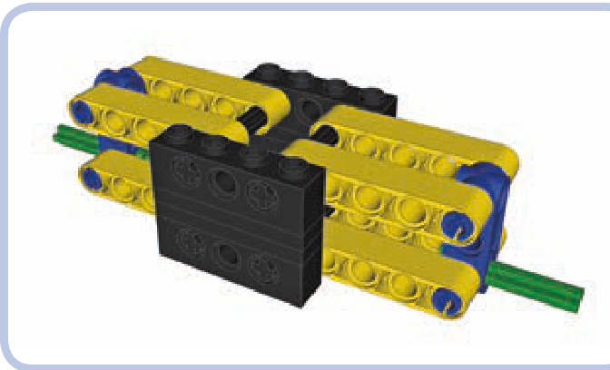
Type: Independent, sprung
The chassis is black, the suspension arms are yellow, the steering arms (not steered in this case) are blue, and the spindles are green. As you see, each steering arm is sus pended on four parallel levers that allow it to move up or down relative to the chassis while keeping the wheel in a vertical position. Consider the examples in Figures 15-8 and 15-9.
One element is missing from these images—the suspension arms need to be actually suspended. In other words, the chassis needs some elastic elements to support it against the suspension arms, or else the entire suspension will collapse. Shock absorbers are well suited and popular in this role (see Figure 15-10). Figure 15-11 provides an example of a model that uses independent suspension.
Advantages: Best suspension type in terms of stability and traction; the orientation of the wheels is maintained at all times
N Disadvantages: Large width; relatively fragile construction
Note that it’s possible to use the same elastic elements for the suspension arms for both wheels, but this will make the suspension dependent—causing one wheel to go up while the other one goes down (see Figure 15-12).
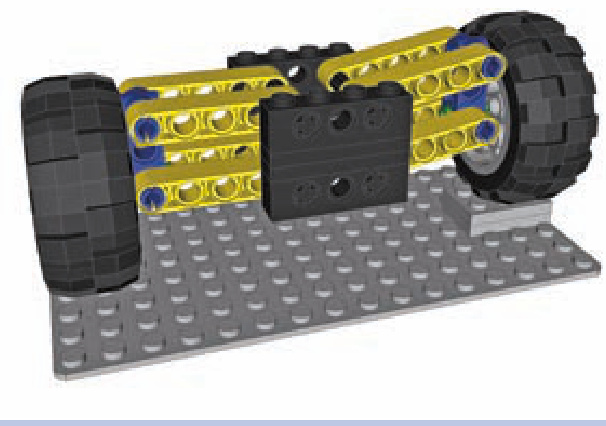
Figure 15-8: Independent suspension with one wheel on an obstacle. Note that the position of the other wheel is unaffected, as it should be with an independent suspension.
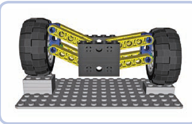
Figure 15-9: Independent suspension with both wheels on obstacles. Both wheels negotiate obstacles independently; hence the name of the suspension type.
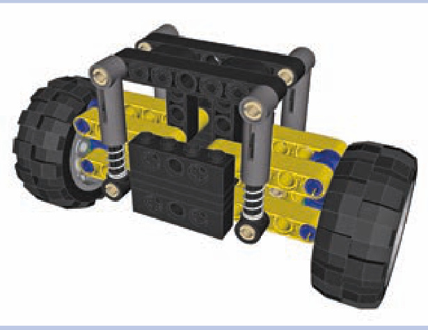
Figure 15-10: Independent suspension with four shock absorbers supporting the chassis against the suspension arms

Type: Independent, sprung
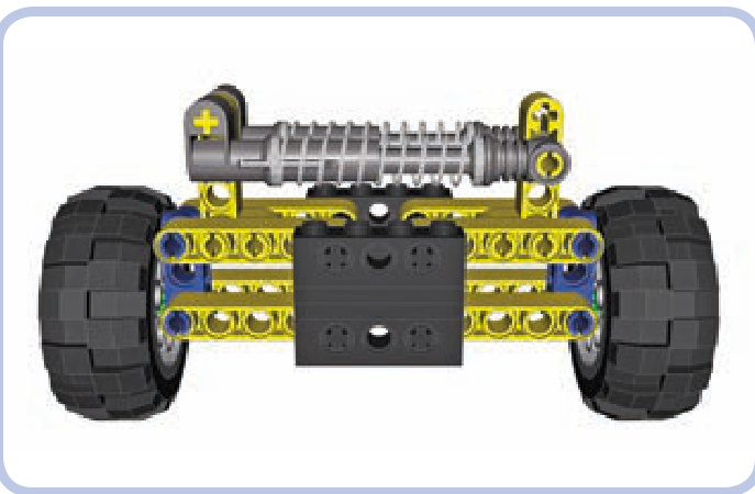
Figure 15-11: My Monster Truck model was a good example of independent suspension. Note that the vertical orientation of both front wheels was identical despite the extreme difference in their heights.
Tatra-type suspension
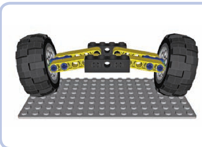
The Tatra-type suspension, also known as a swing-arm suspension, was developed and patented by the Tatra company, which uses it almost exclusively. The Tatra-type suspension is a simpler variant of the independent suspension that uses only two levers per wheel as suspension and keeps the spindles perpendicular to the suspension arms at all times. This means that the orientation of the wheels changes as they negotiate obstacles. By default, the wheels are tilted, as shown in Figure 15-13, a unique feature for this suspension type.
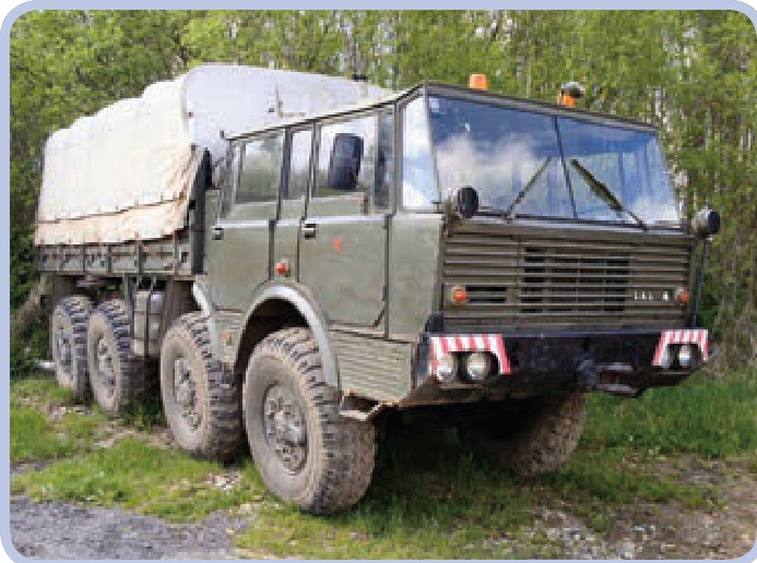
Figure 15-12: A suspension with shock absorbers supporting the suspension arms against each other (left and right). This solution will keep the chassis stable, but the suspension will become dependent.
Figure 15-13: The default position of the Tatra-type suspension offers extra ground clearance. This “bowed” look can be mistaken for damage or warping.
Other than the tilting of the wheels, the Tatra suspension, shown in action in Figure 15-14, shares all the qualities and properties of a regular independent suspension. It is valued for the robustness coming from its simplicity, and it performs very well on rough terrain (Tatra off-road trucks are nothing short of legendary); its only downsides are inferior sideways stability and poor tire wear. Such a suspension is viable only for heavy off-road vehicles.
Advantages: Simpler, more robust than a typical independent suspension
Disadvantages: Slightly inferior traction because of the wheels’ changing orientation; inferior sideways stability
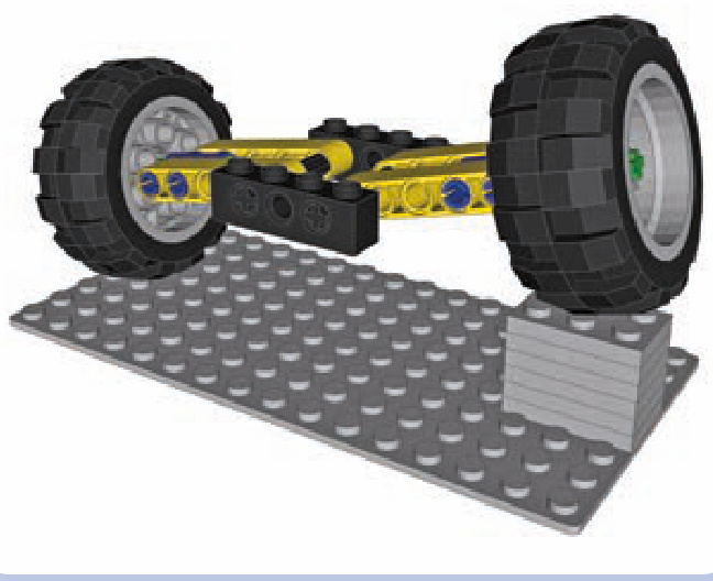
Figure 15-14: The Tatra-type suspension negotiating an obstacle with one wheel. Note that the orientation of the wheels changes in the process, which is why this suspension requires tires with a round profile (balloon tires) to maintain good traction.
pendular suspension
Type: Dependent, unsprung
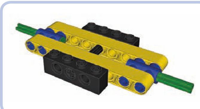
A pendular suspension is the simplest and the most robust kind of suspension: It allows the axle to swing back and forth on a single point just like a pendulum. As it’s only one solid element, it can be very narrow and built with just a few pieces. Figure 15-15 shows a pendular suspension in action.
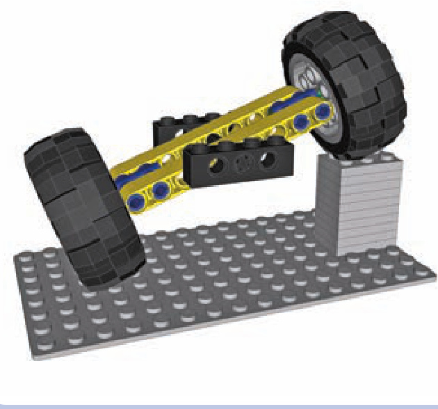
Figure 15-15: A pendular suspension negotiating an obstacle with one wheel. Note that the chassis, which is connected to the axle by the axle going through its center, is raised by 50 percent. This is generally bad for stability and for the driver’s comfort.
On the downside, pendular suspension systems take a lot of space in the chassis, requiring the model to have a large gap in order for the suspension to fit. The pendular suspension system can’t be sprung, but it often requires shock absorbers (see Figure 15-16) or other elastic elements to keep it stable—unless you arrange the suspended axles of your vehicle so as to provide three or more fulcrums. The longitudinal axle that goes through it is also the only way to transfer the drive to the suspension from the chassis. So the longitudinal axle is used as the driveshaft, which means that this suspension is mounted on the driveshaft and presses on it, creating extra friction.
Advantages: Simplest and most robust suspension type; can be very narrow
Disadvantages: Unsprung; takes a lot of space in the chassis; adds extra friction on the drivetrain (see “Pendular Suspension with Turntables” on page 210 for a means of mitigating this effect)
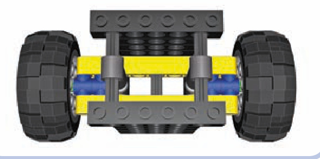
Figure 15-16: A pendular suspension stabilized with a pair of shock absorbers. Note that the shock absorbers work against each other and need to be half compressed when the suspension is level. When one wheel goes up, the absorber close to it is compressed more, and the other one is compressed less.
trailing arm suspension (floating axle suspension)
Type: Dependent, sprung
A floating axle suspension (or live axle) is a sprung variant of the pendular suspension. It’s a single solid element that has no rigid connections to the chassis whatsoever; instead, it is connected to it by a number of links that form a linkage allowing it to move up and down and tilt to the sides. It can be just as narrow and robust as a regular pendular suspension, and it doesn’t press on the driveshaft. However, it takes an extreme amount of space in the chassis because of the linkage that comes between it and the chassis.
Floating axles can be extremely complex. The variant we will focus on is a simple one (see Figure 15-17): It uses four links and two independent suspension arms above the actual axle that need to be supported by some elastic elements. It also uses a driveshaft with a single universal joint on it to keep the axle aligned with the chassis.
Advantages: Combines all the advantages of pendular suspension with being sprung and usually more stable Disadvantages: Takes a lot of space in the chassis
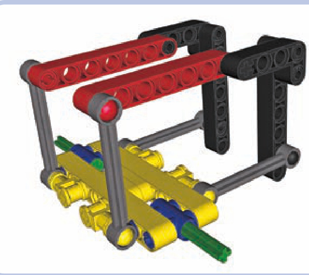
Figure 15-17: A floating axle negotiating an obstacle with one wheel. Note that the orientation of all four links is changed, while the chassis’ orientation remains the same.
Choosing the best type of suspension for the job is always a little tricky, but your decision can be made easier by considering what is used in real vehicles. For example, luxury cars usually have full independent suspension to improve passengers’ comfort, while construction vehicles— such as front-end loaders, for instance—usually have pendular suspension because the heavy loads they are handling would affect a sprung suspension too much.
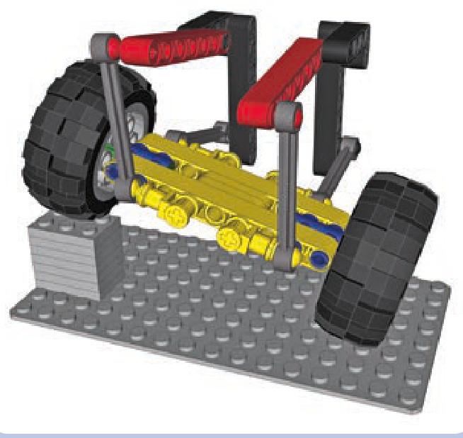
driven and suspended axles
Axles that are driven and suspended at the same time are relatively easy to build, and they’re important as the vast majority of vehicles has at least one.
pendular suspension with turntables
As explained earlier, the pendular suspension has the disadvantage of being attached to the chassis by the driveshaft, which is subject to stress generated by the vehicle’s weight. This single point of stress creates additional friction; however, this problem can be prevented almost completely by using a Technic turntable to attach the suspension to the chassis (see Figure 15-18), as an alternative to using ball joints. The turntable then supports the weight of the vehicle, while the driveshaft can go through the middle of the turntable nearly unburdened.
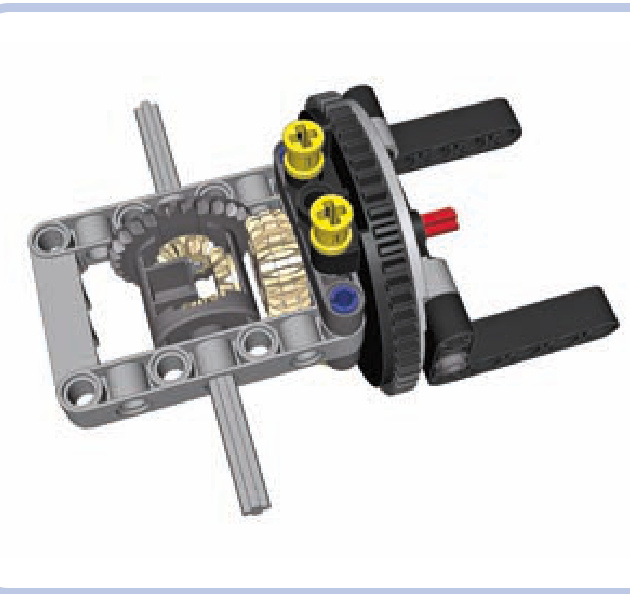
Figure 15-18: The newer type of Technic turntable is used to attach the suspension (the light grey frame) to the chassis (the black L-shaped beams). A turntable is a very rigid structure capable of supporting huge loads while adding minimum friction to the driveshaft (red) that goes through it.
Note that the large diameter of the turntable is bad for ground clearance, so it’s a good idea to use this design in concert with portal axles. Also note that the hole in the turntable is large enough to install a differential case in it, which can be used to transfer both drive and steering through a single turntable (see Figure 15-19).
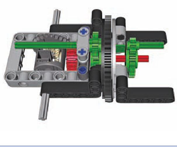
Figure 15-19: As an empty differential case rotates freely on an axle, it can be used to transfer steering over the driveshaft. Here, red pieces are acting as a driveshaft and green pieces are acting as a steering shaft without interfering with each other. Note that the steering shaft is slightly affected when the suspension tilts and the turntable rotates. Still, it’s a useful solution when the driveshaft and steering shaft need to be connected to the suspension from the same side.
a stabilized pendular suspension
This is a simple, robust, and compact suspension kept stable by four shock absorbers. Keep in mind that absorbers of various length and hardness can be used.
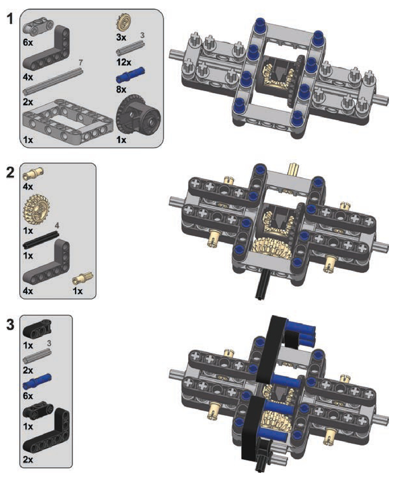
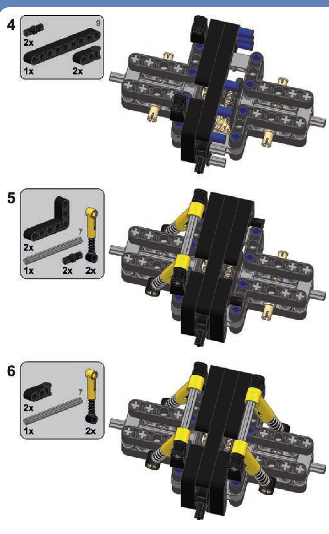
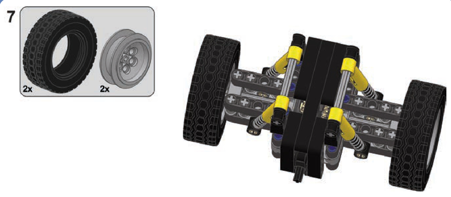
portal axles (geared hubs)
Portal axles are axles with gear hubs on the wheels that increase both ground clearance and the gear reduction of the drivetrain, as Figure 15-20 shows. Practically any axle, including a steered one, can have gear hubs and become a portal axle at the cost of increased width. The most popular are hubs with a 24-tooth and 8-tooth gear combination, providing a 3:1 gear reduction. The 3:1 gear reduction means not only that torque on the wheels is increased three times but also that other parts of the drivetrain handle only a
third of the overall load. This is very useful for steered axles because it allows us to use universal joints, which could otherwise be damaged by the load.
There are a number of ways to build narrow, strong gear hubs. The easiest one, however, involves a ready-made LEGO gear hub housing: a #92908 piece, into which a #92909 is inserted to support the wheel (see Figure 15-21). We will refer to this very convenient combination as a LEGO hub. Figure 15-22 shows a model that makes use of LEGO hubs.
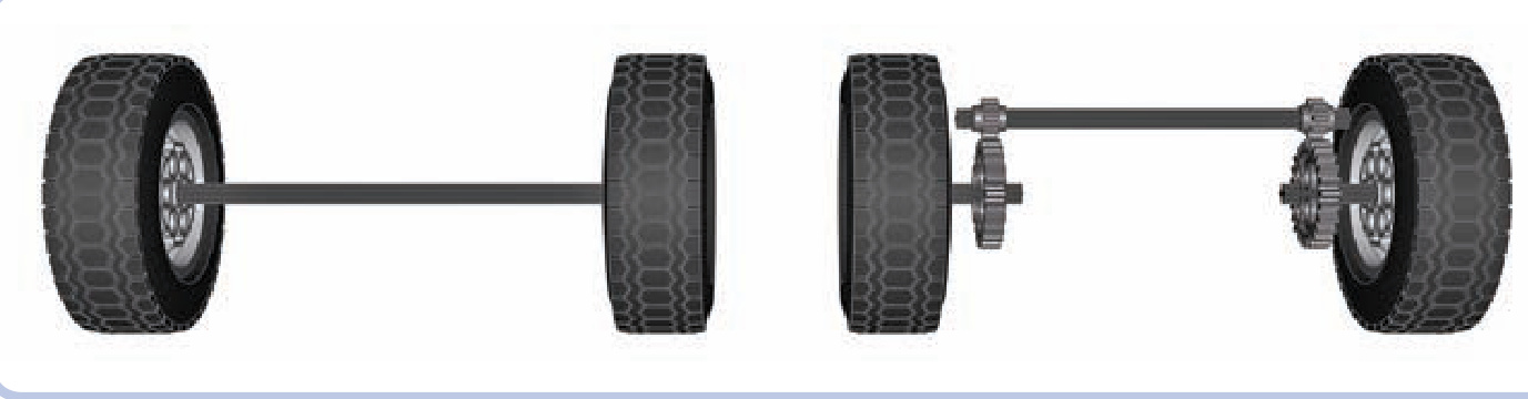
Figure 15-20: A regular axle (left) and portal axle (right)
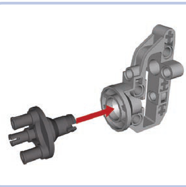
Figure 15-21: Pieces #92909 (left) and #92908 (right) together form a so-called LEGO hub.

Figure 15-22: My model of the MRAP vehicle made use of LEGO hubs to achieve an impressive ground clearance exceeding 6 studs.
a stabilized pendular suspension with a portal axle
This is a variant of the previous design with hubs added to make it a portal axle.
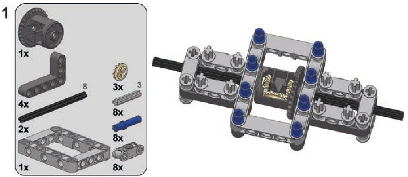
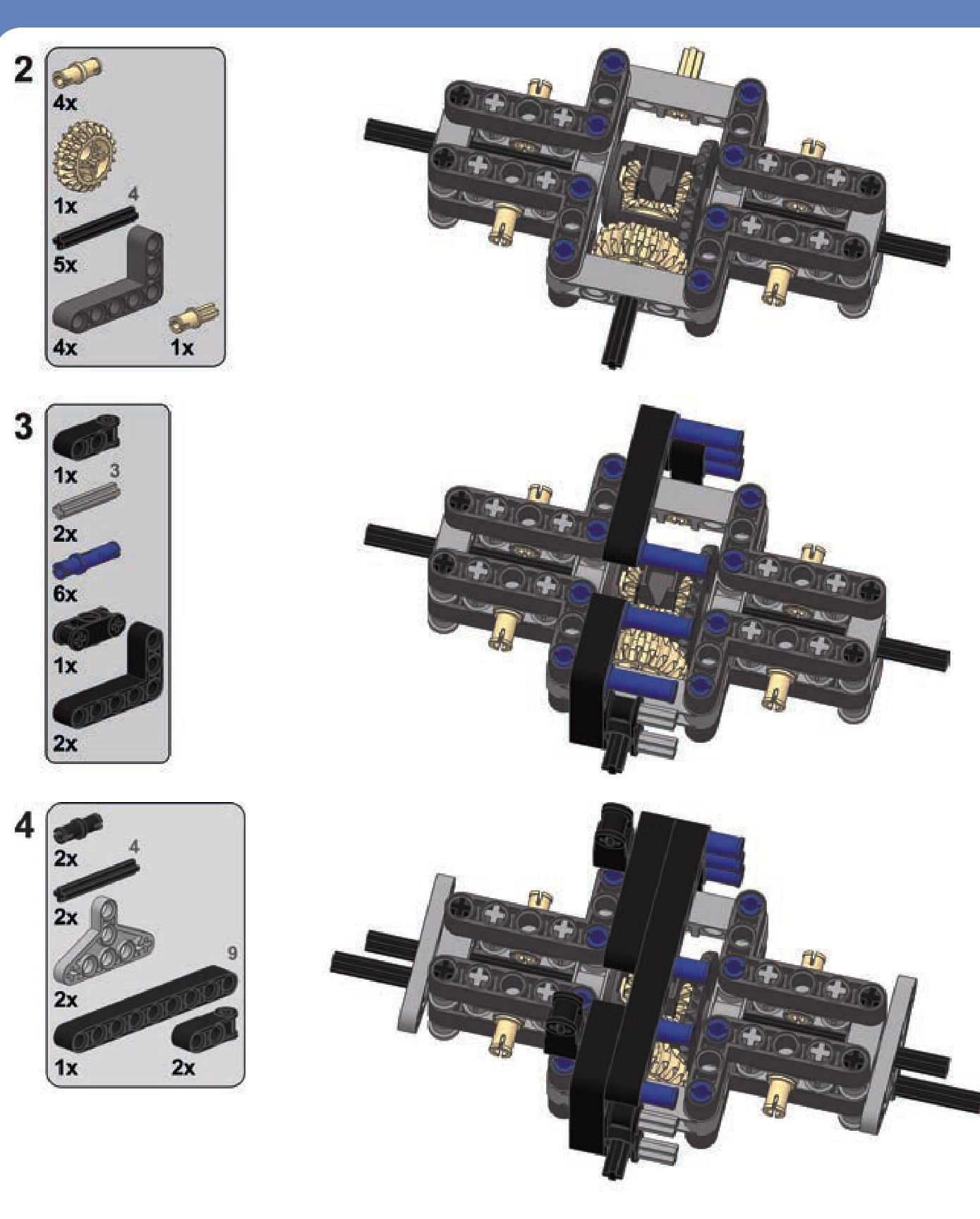
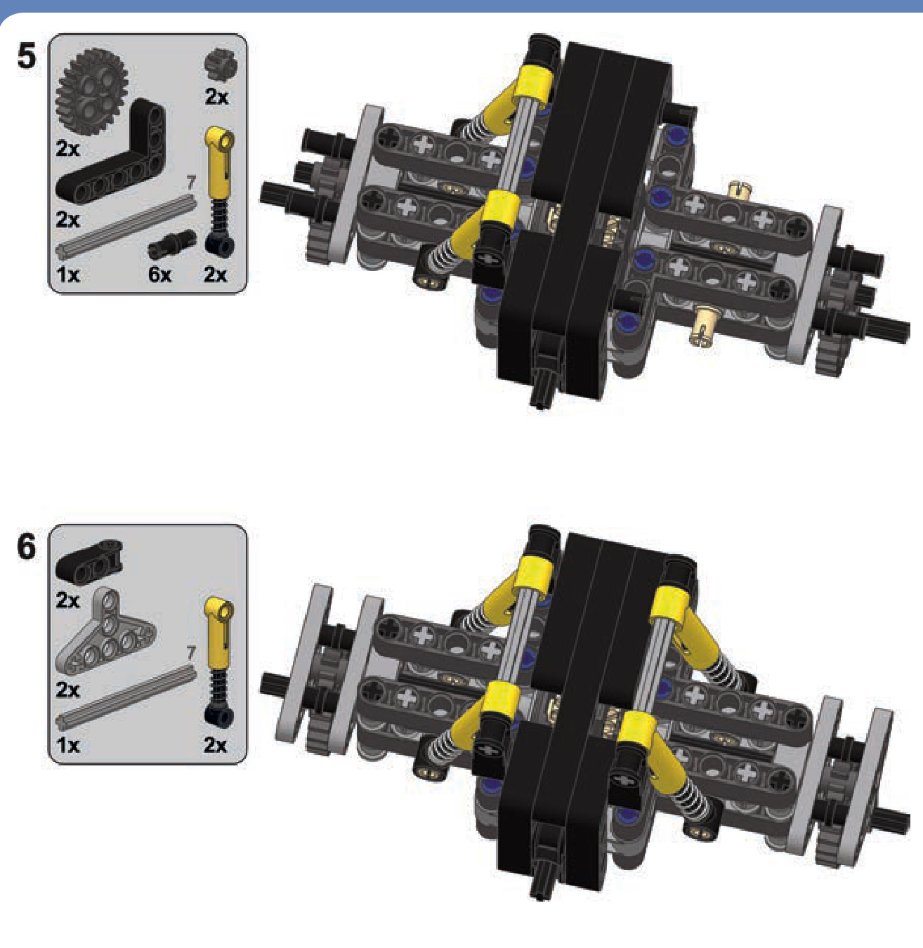
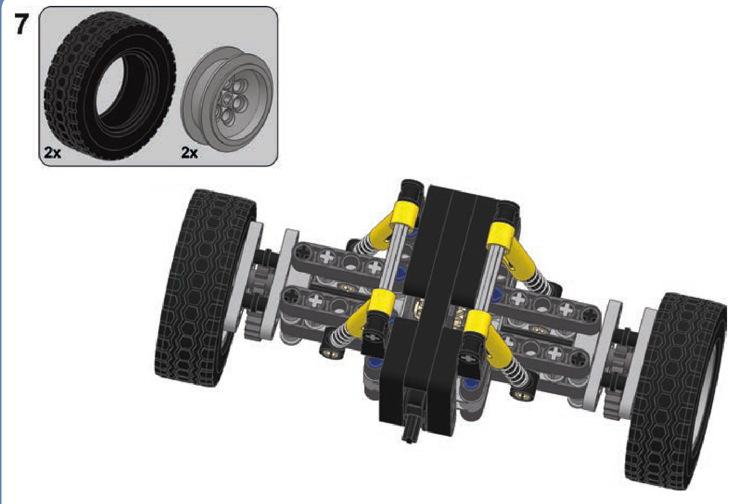
a Tatra-type suspension stabilized with four shock absorbers
This is a simple, robust suspension without a differential, well suited for rough terrain. Remember to set up the shock absorbers so that the wheels are tilted slightly downward when the suspension is unloaded.
Not e It’s possible to convert this design to use a portal axle, but it’s not recommended with this suspension as doing so would decrease its sideways stability.
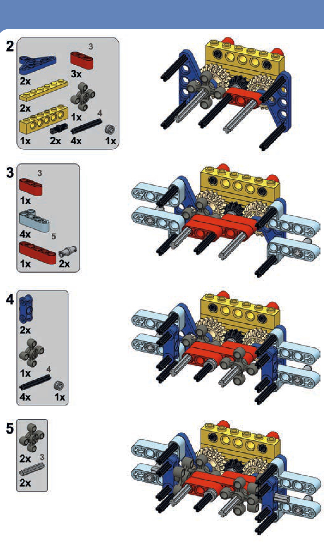
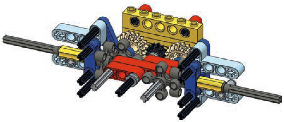
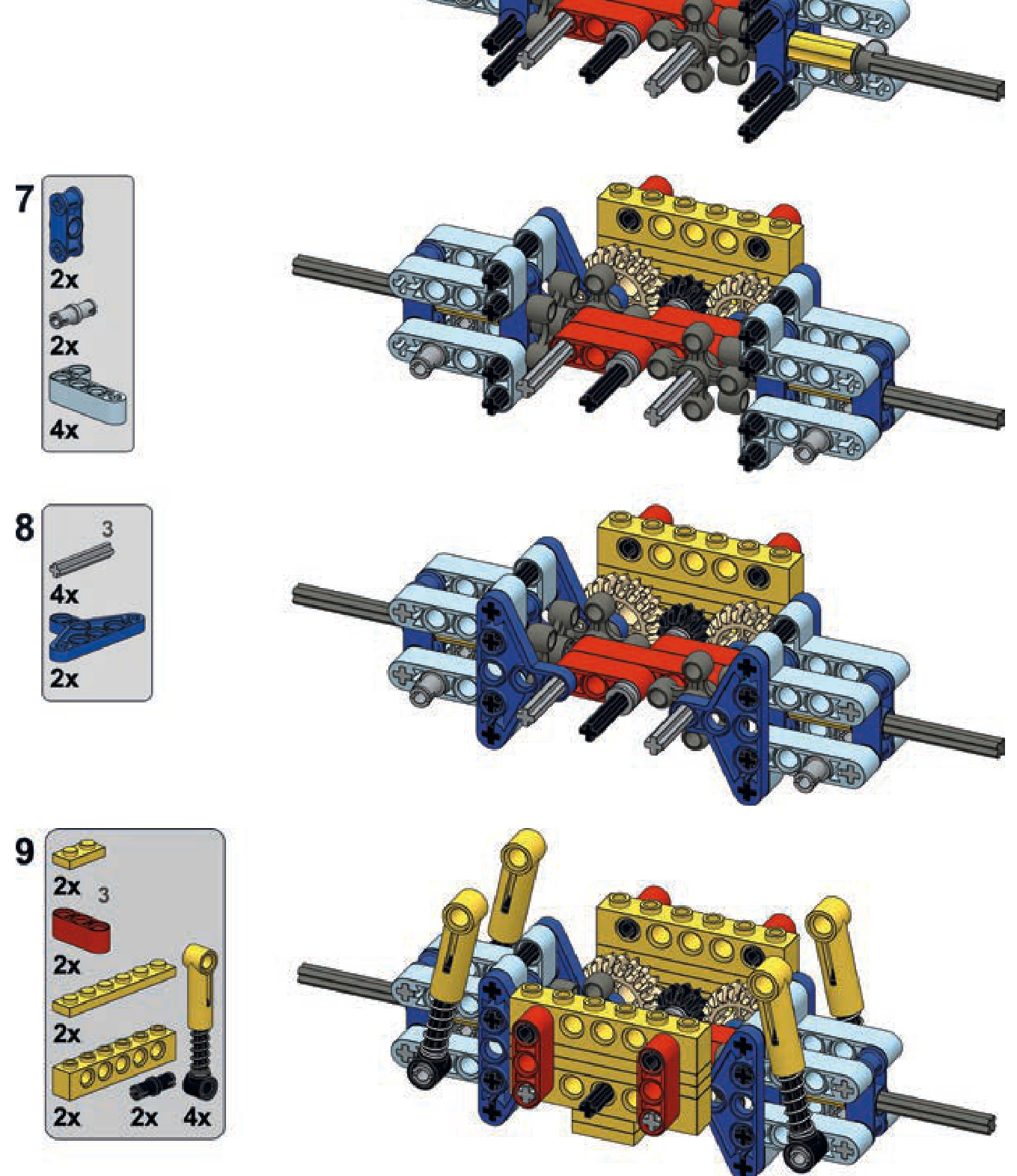
an independent suspension
This is a typical independent suspension. It’s wide but provides good overall performance.
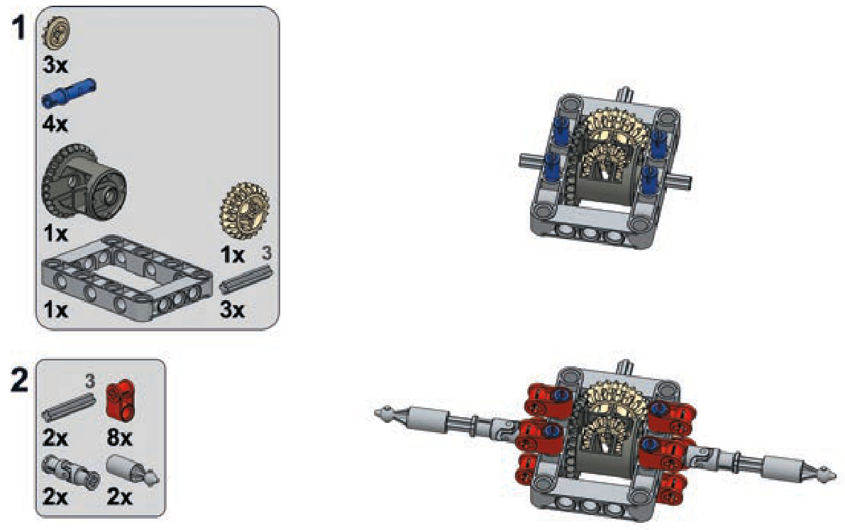
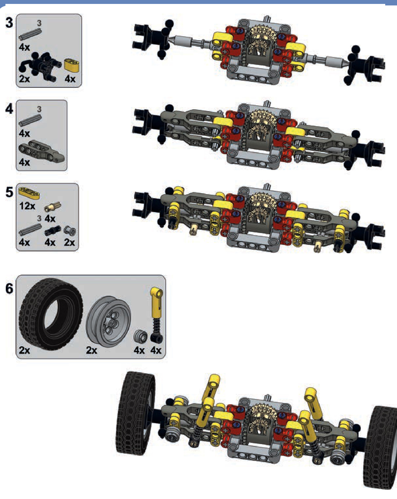
a floating axle with four links
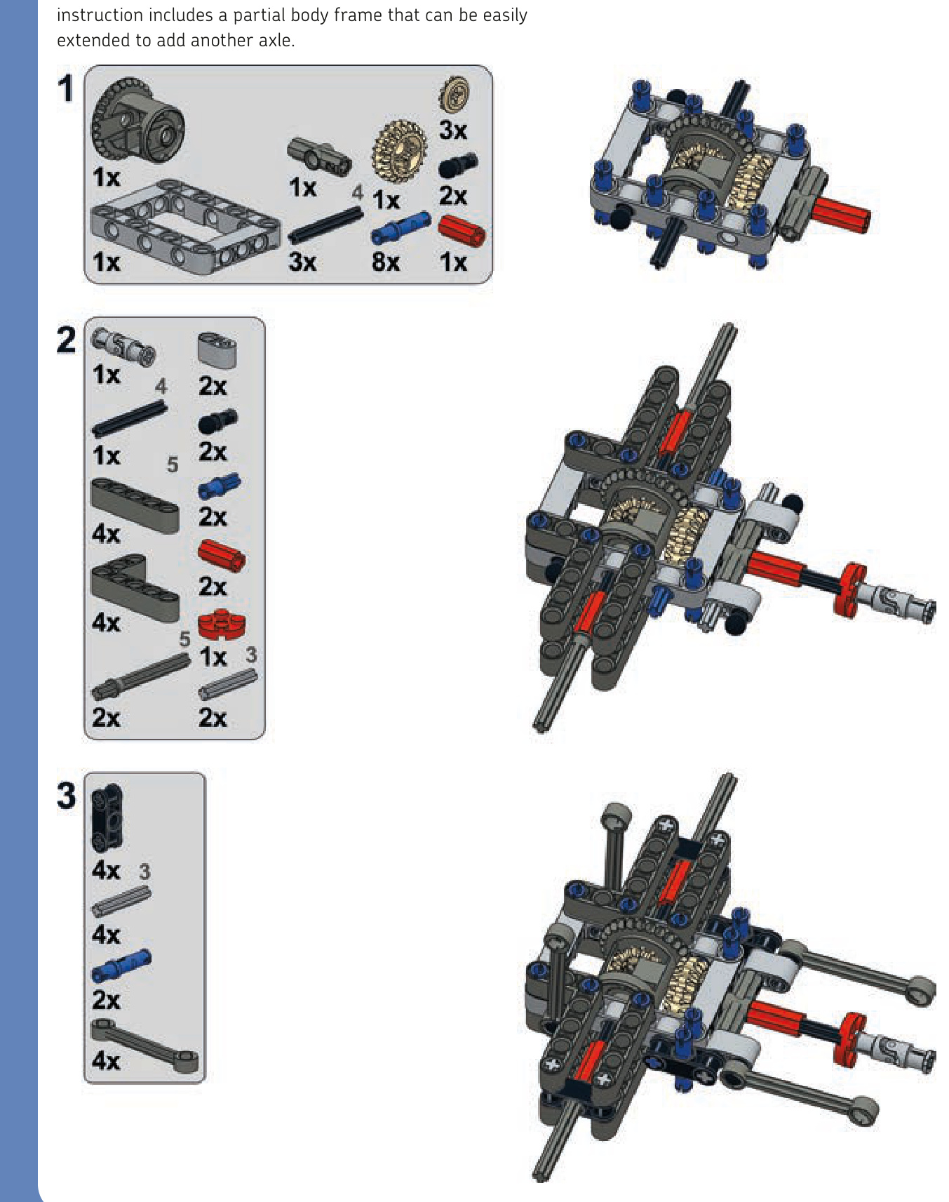
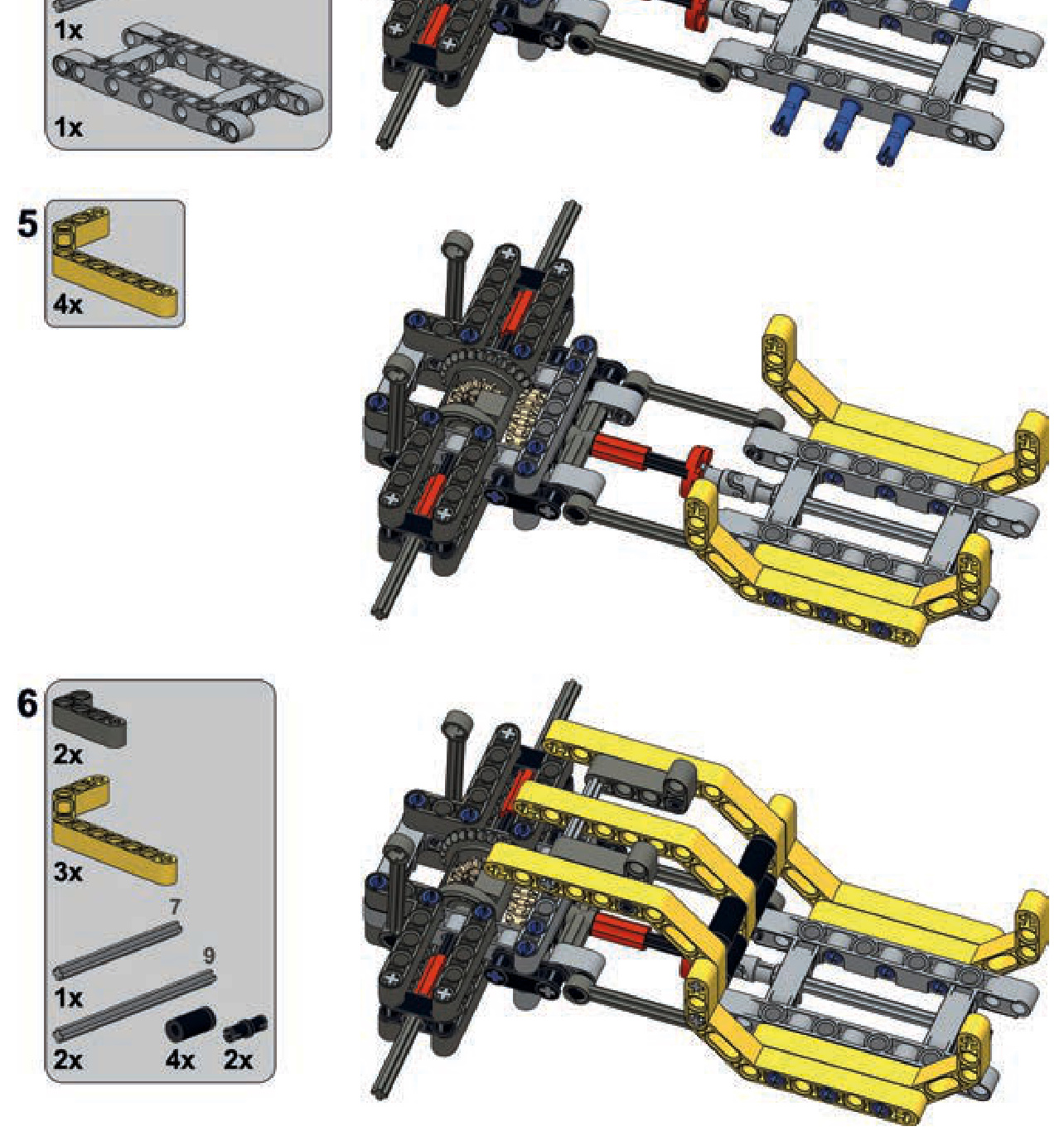
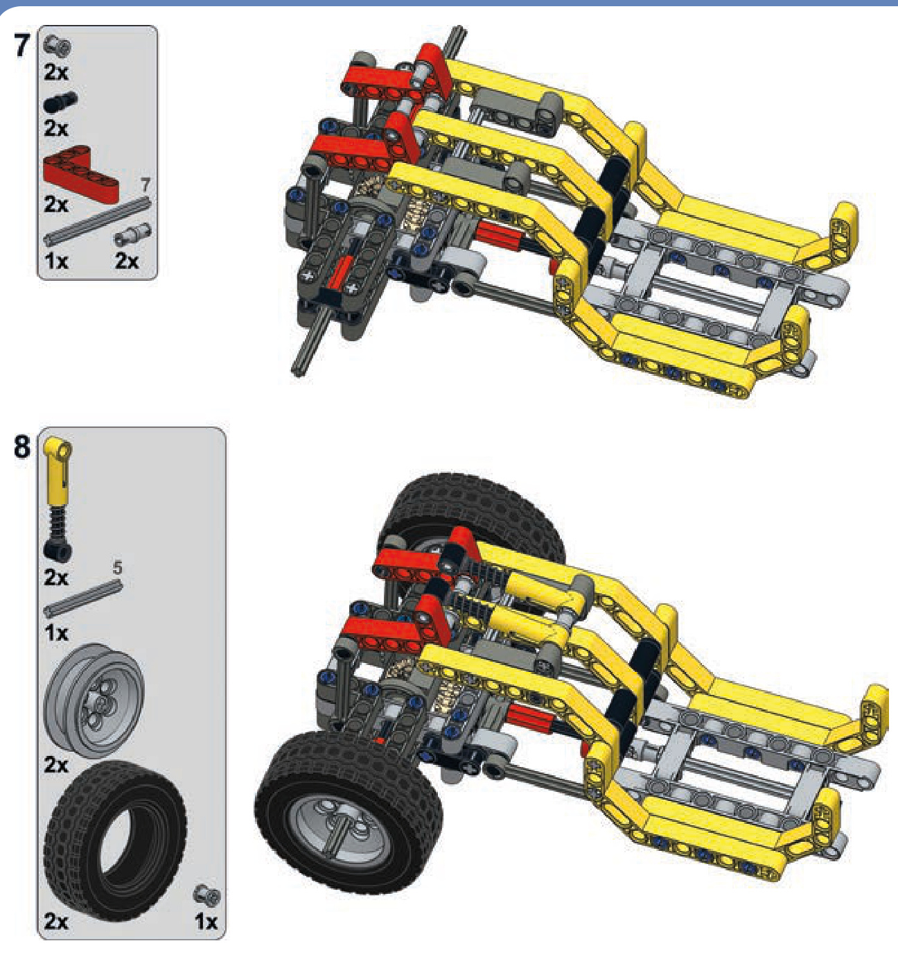
steered and suspended axles
a pendular steered axle
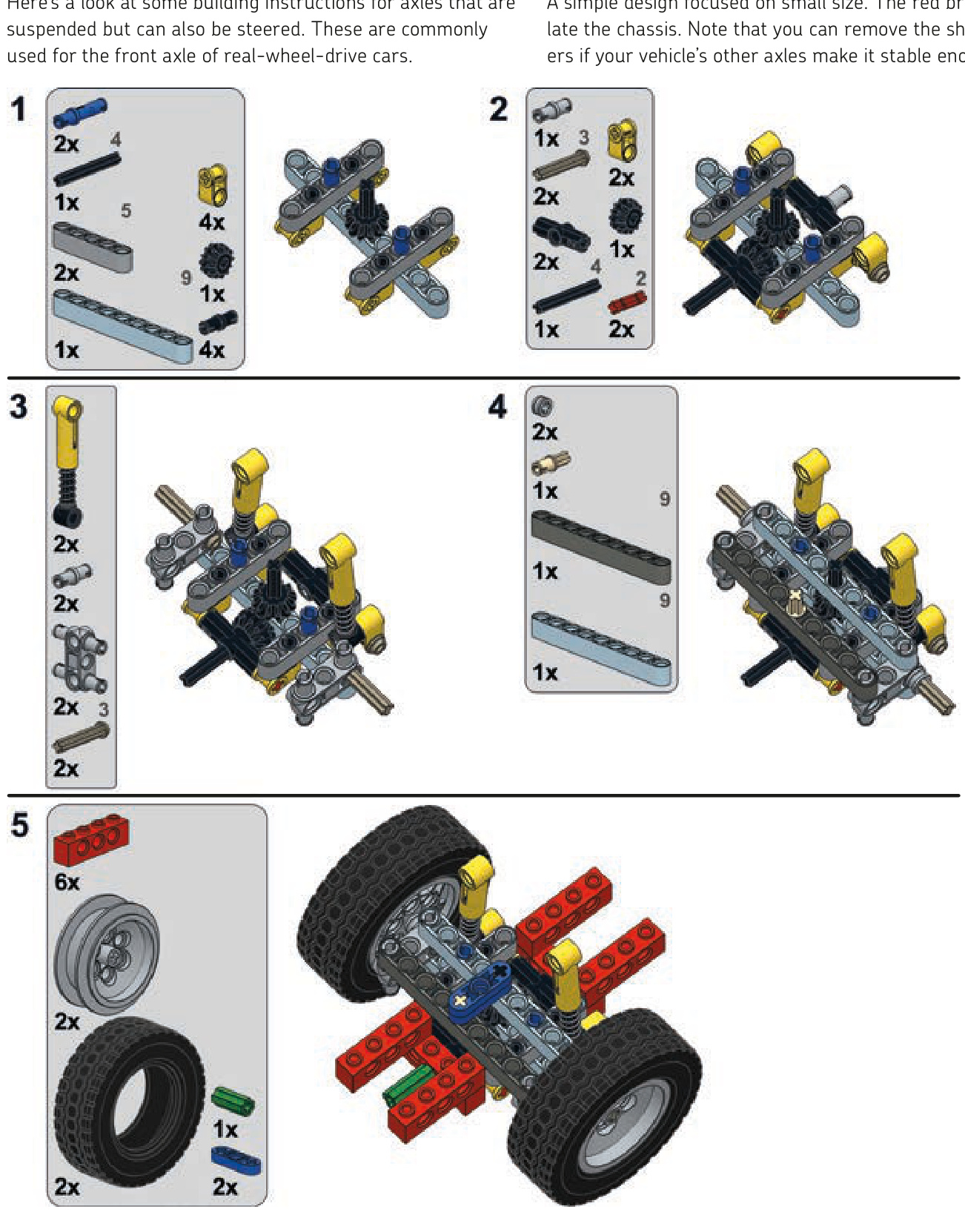
an independent steered axle
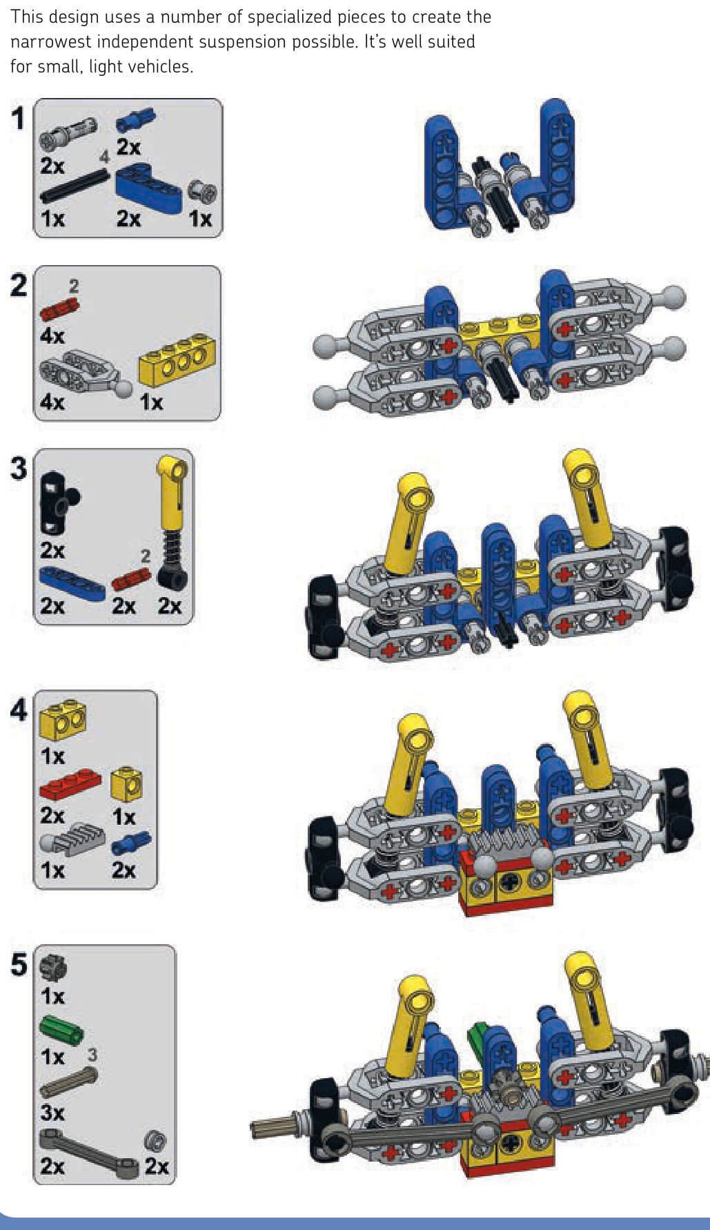
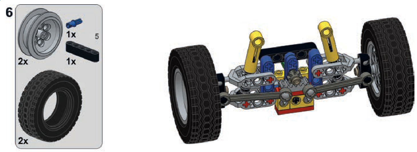
driven, steered, and suspended axles
an independent axle
Here are building instructions for the most complicated category of axles.
This axle is just slightly more complicated than the version without steering.
Not e There is an older version of this suspension using different (older) pieces in the 8880 LEGO set.
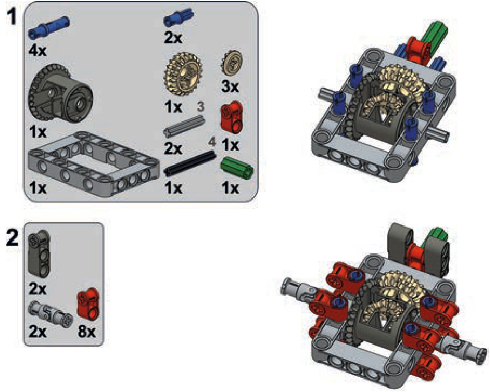
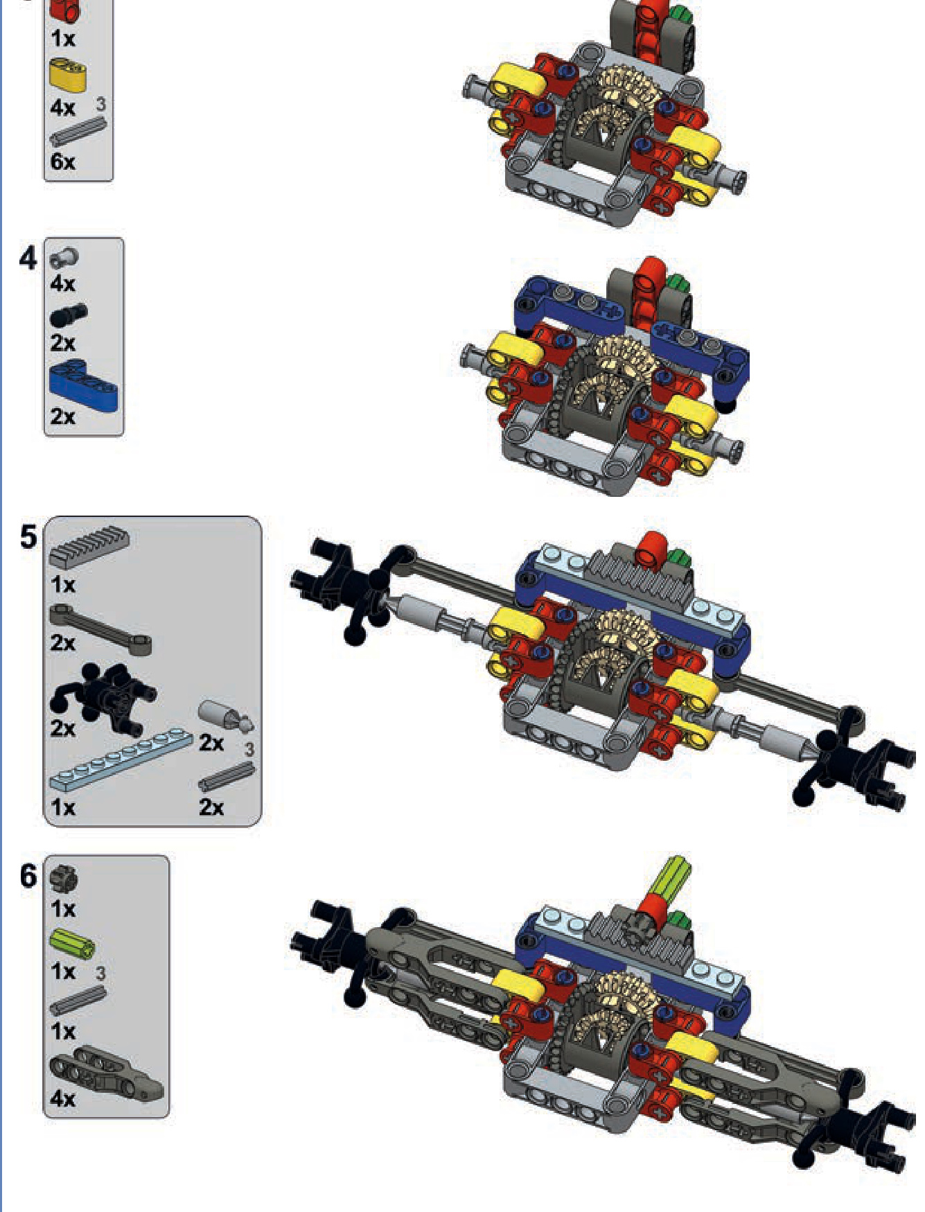
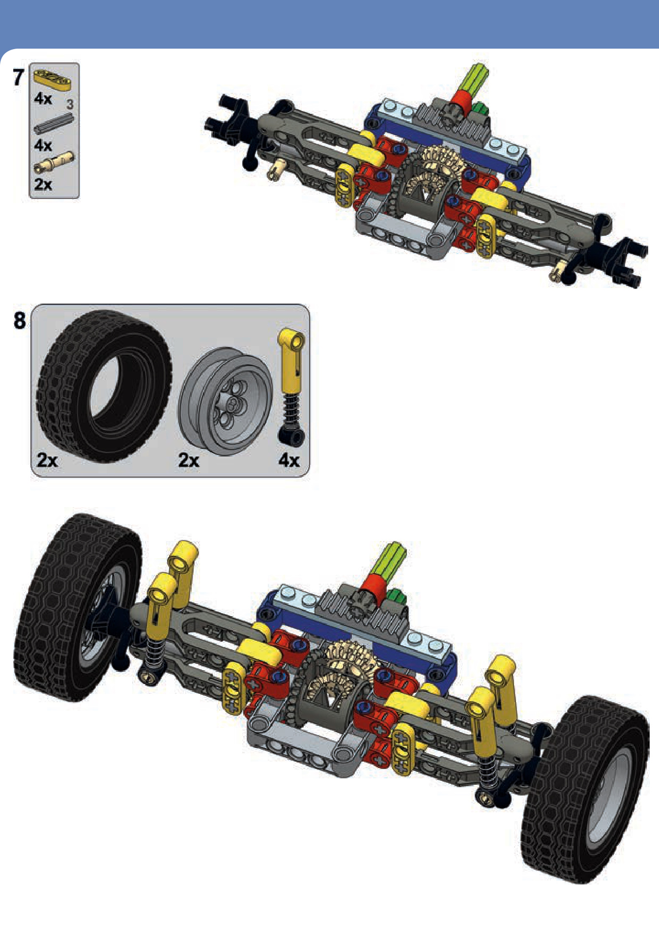
a heavy-duty pendular portal axle
This is a complex and extremely robust suspension designed for very rough terrain. It includes knob gears instead of a differential, and it consists mostly of basic studless pieces.
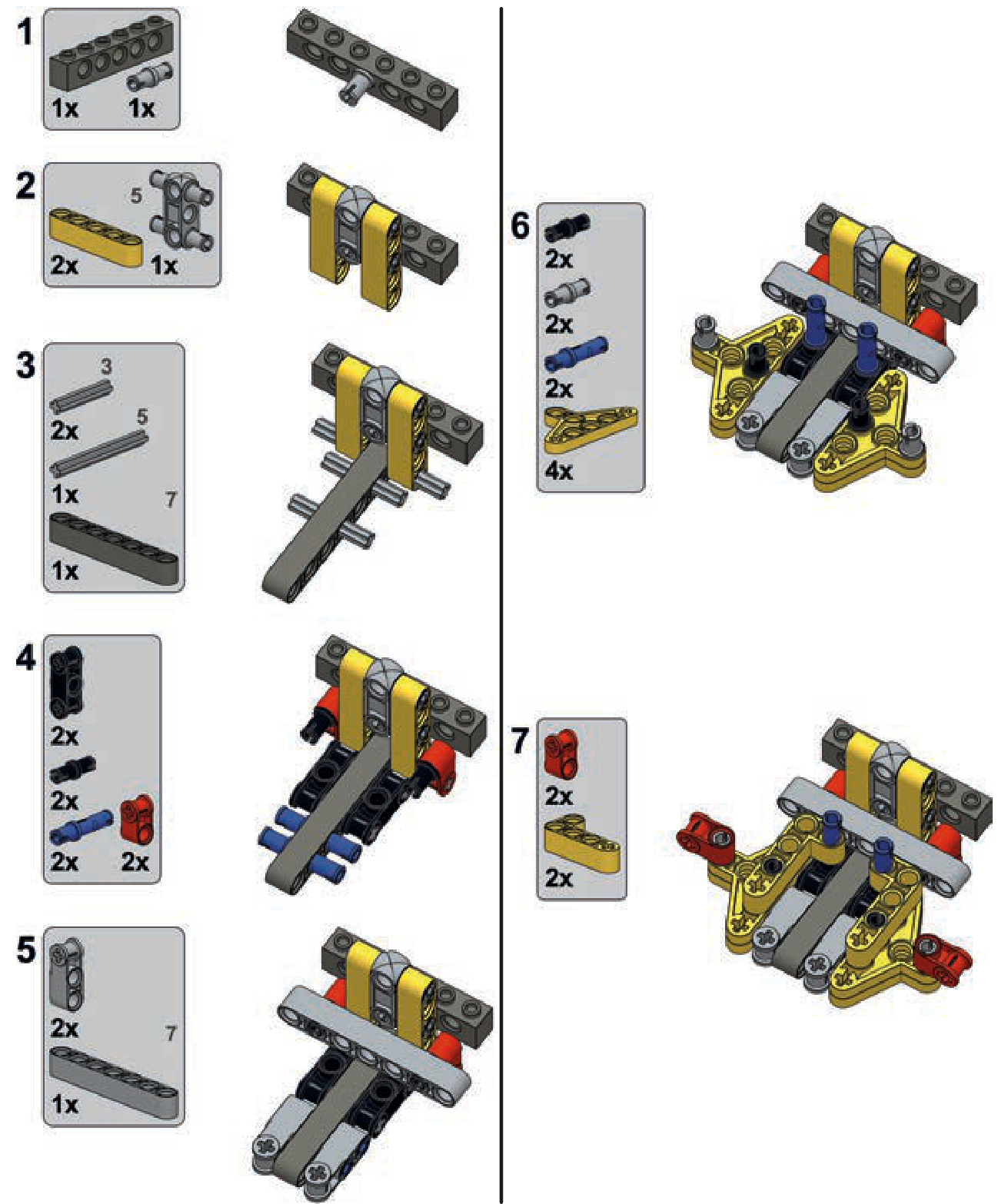
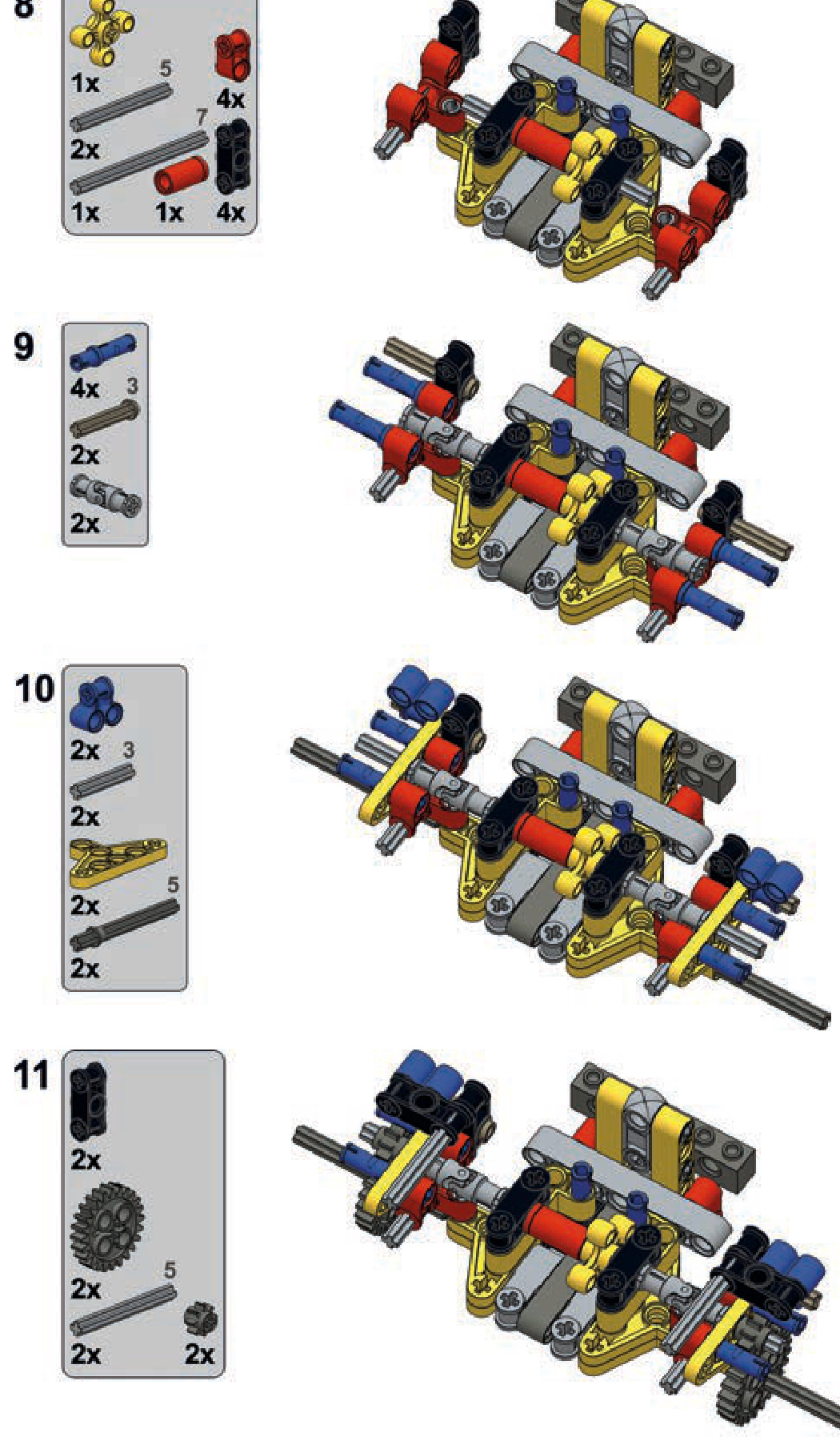
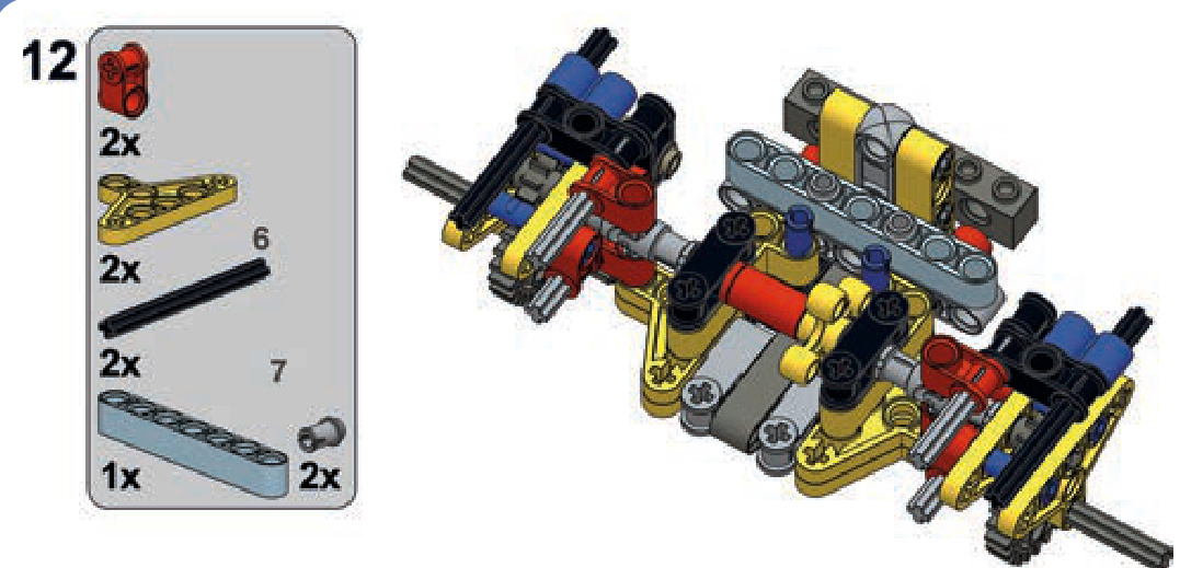
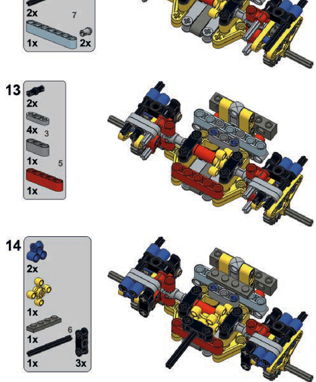
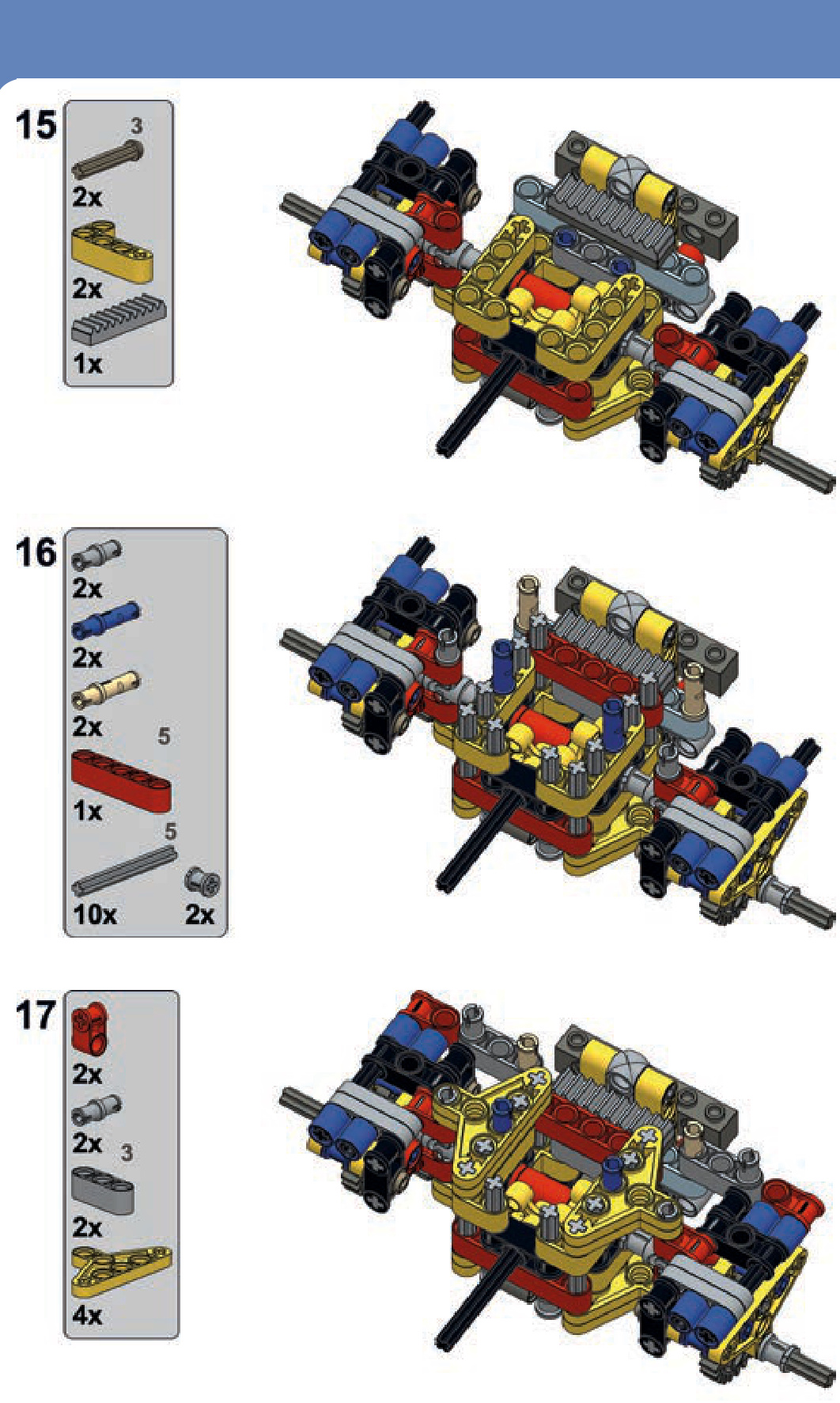
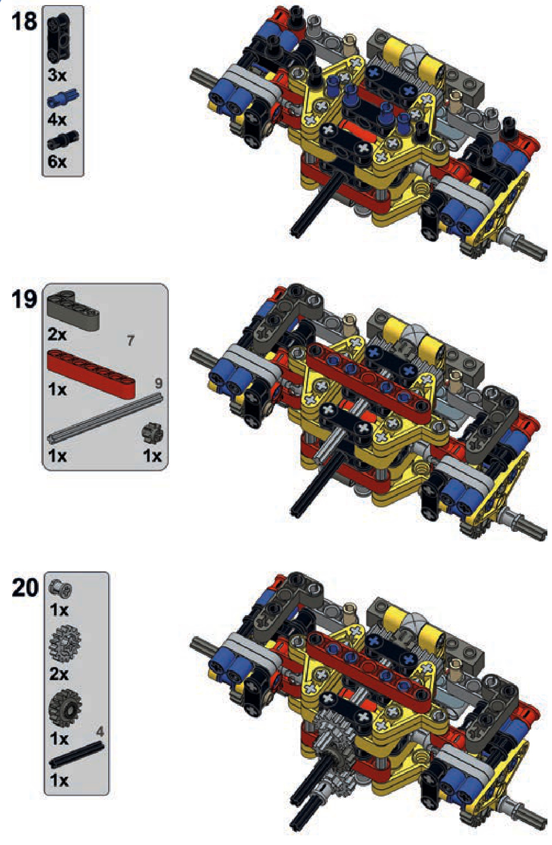
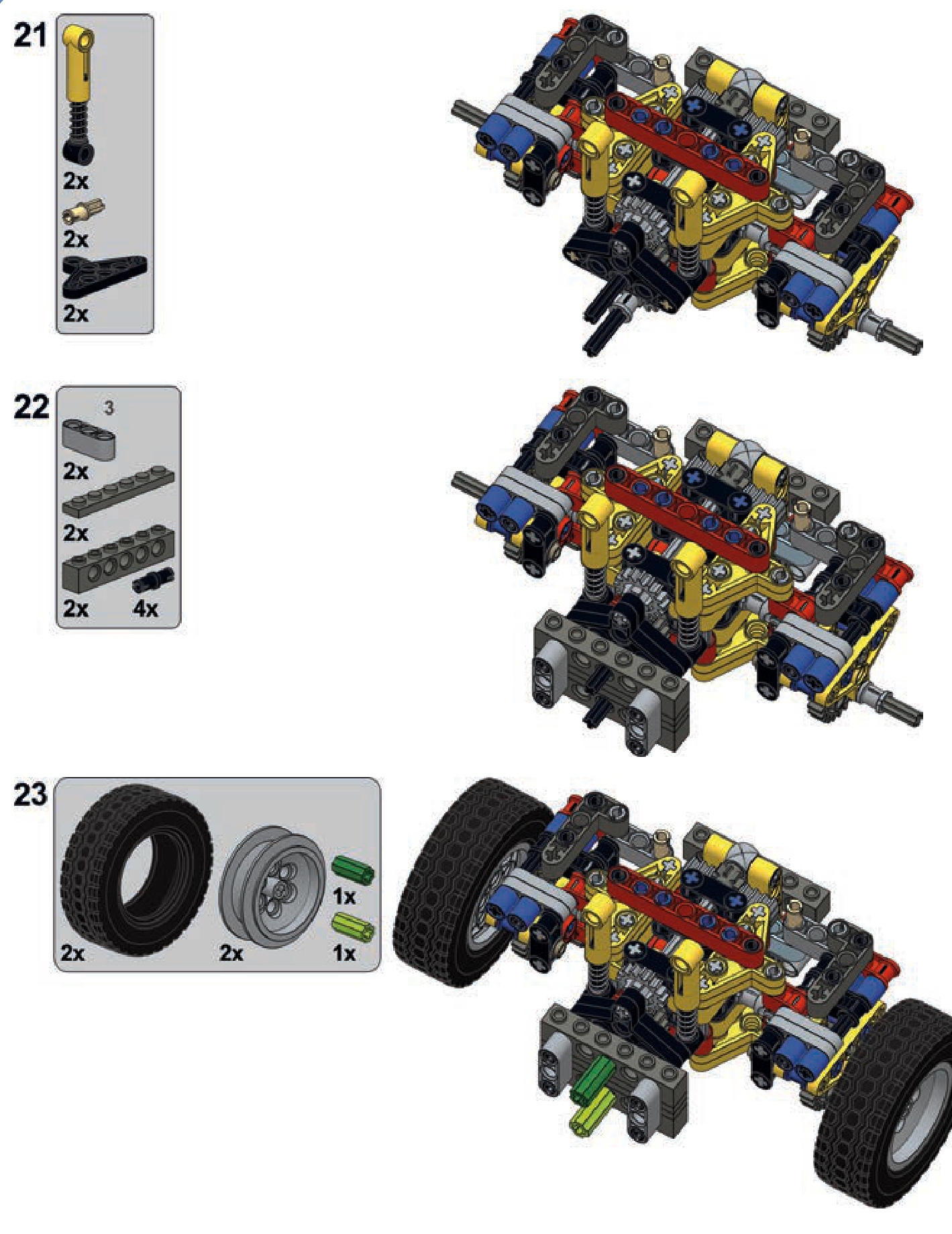
a pendular axle with a worm gear
This is a compact suspension that uses the middle differential variant and a worm gear. This makes it well suited for use with motors that require substantial gear reduction. At the same time, it generates large backlash because of the two 8-tooth gears meshed with one another.
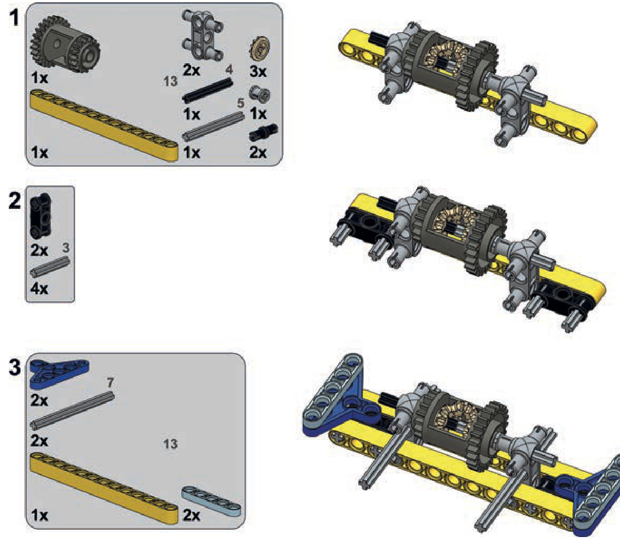
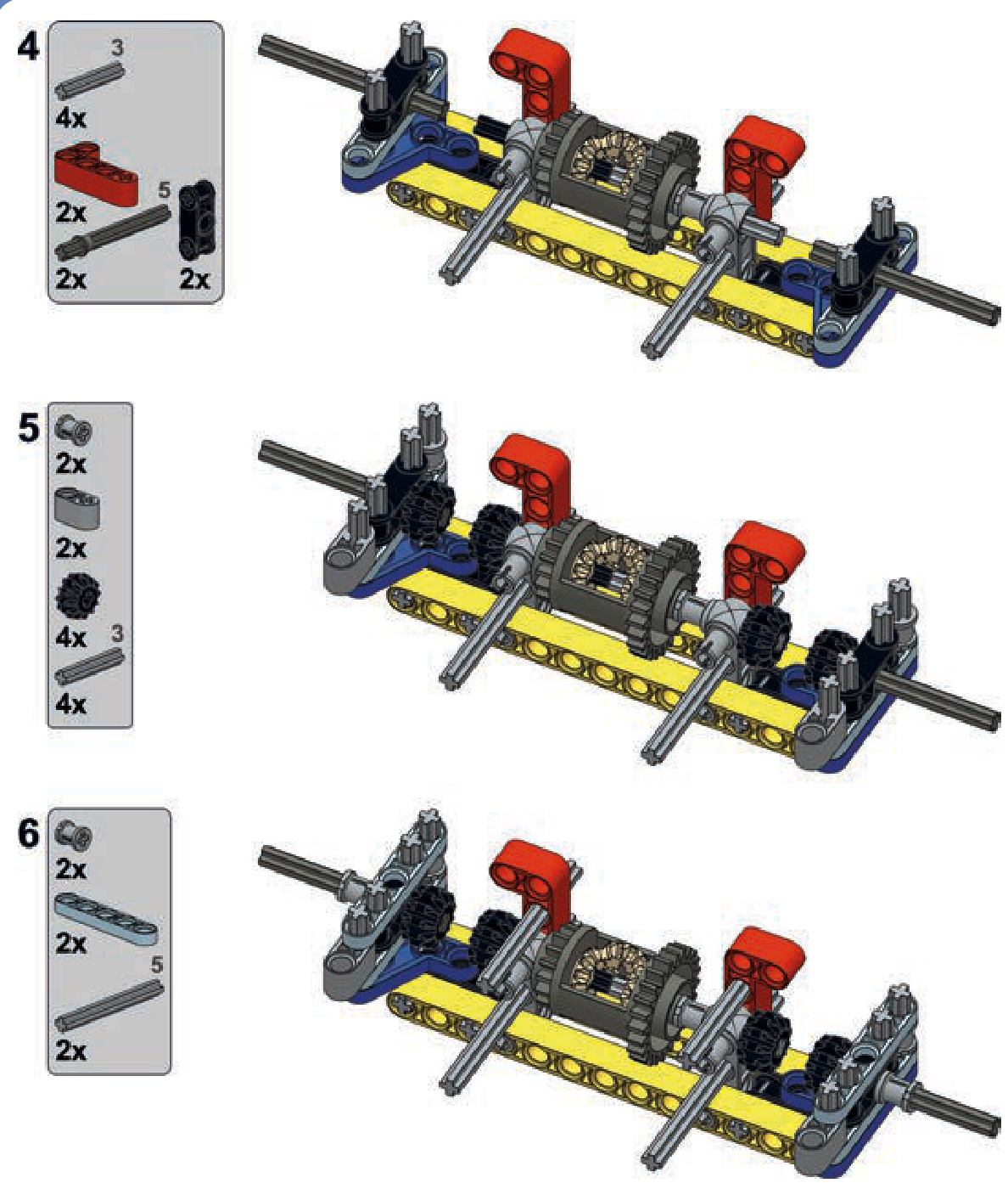
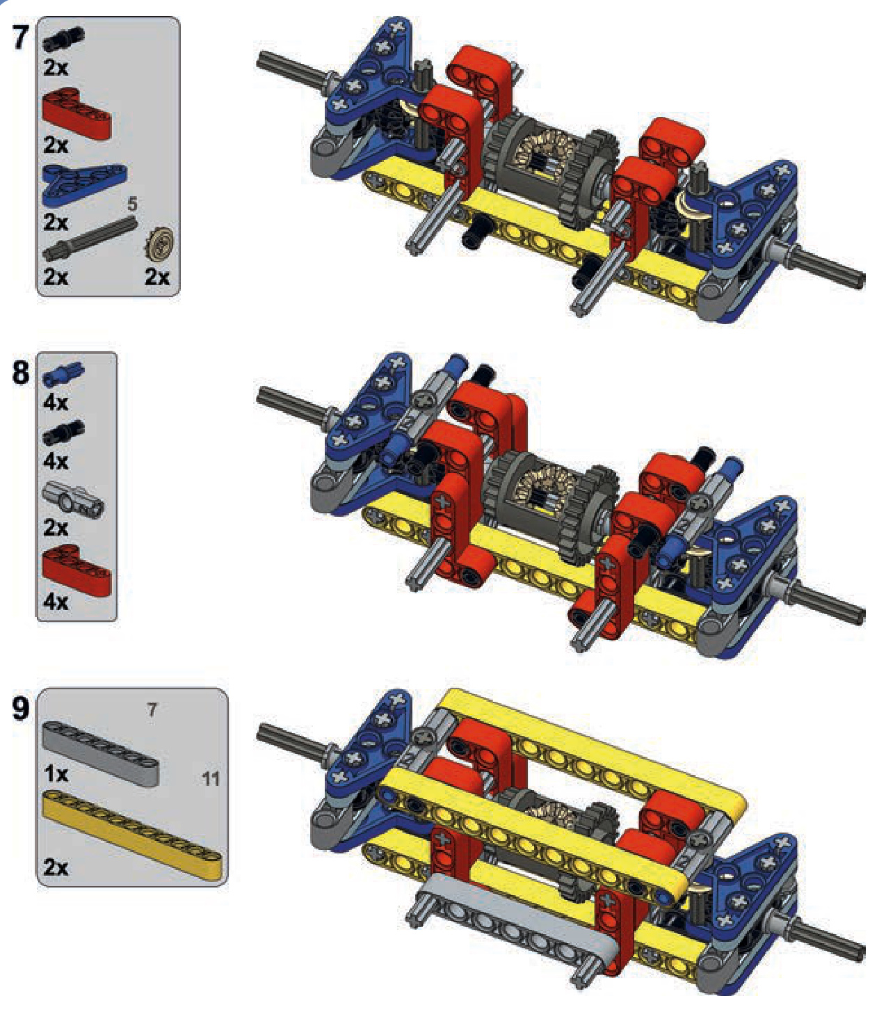
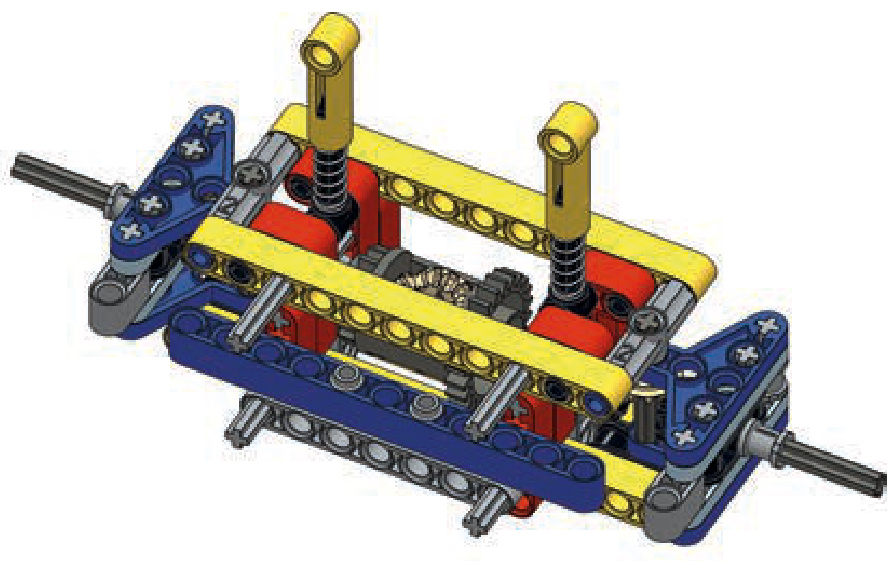
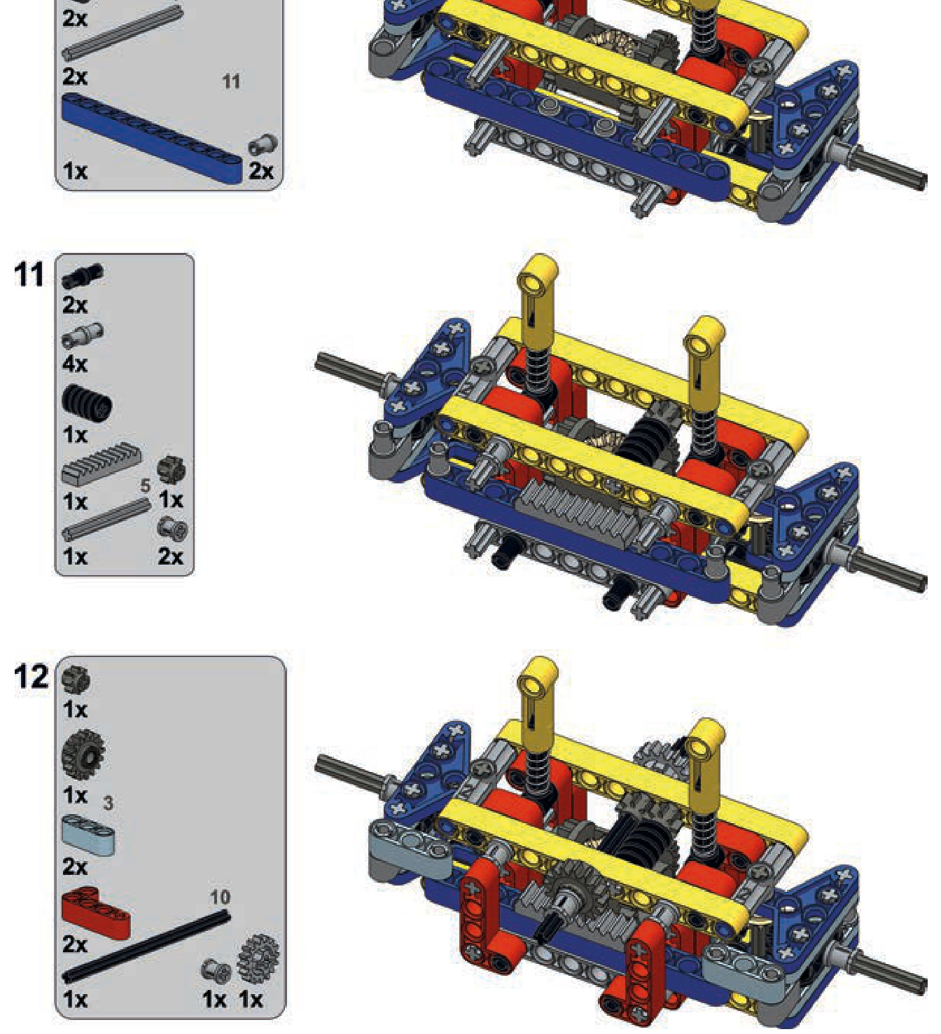
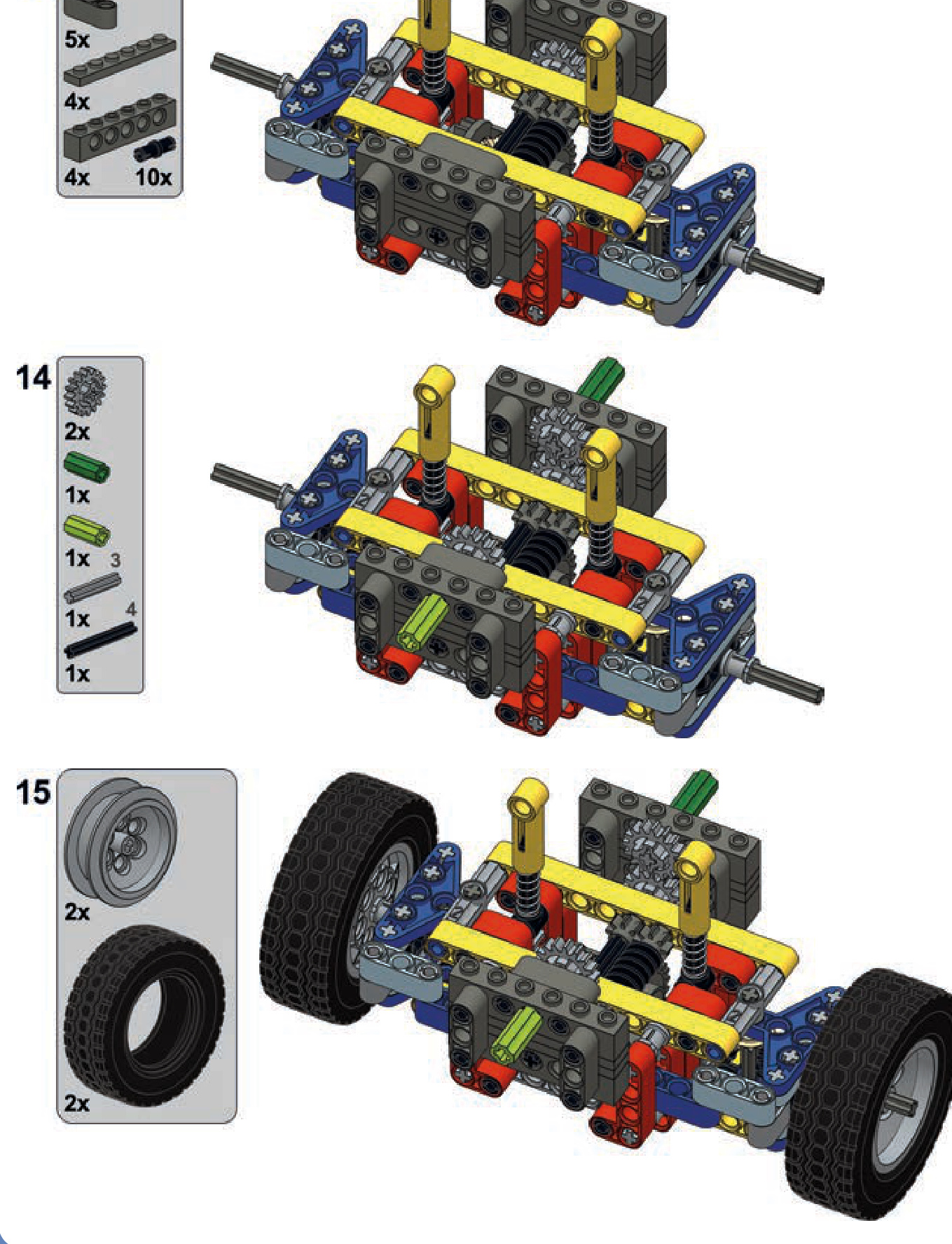
16
tracked vehicles and suspensions
Tracked vehicles are superior to wheeled vehicles for covering rough terrain. In a manner of speaking, tracks allow tanks and construction vehicles to “carry their own road” wherever they go. To create tracked LEGO vehicles, we have two options: rubber tracks and hard plastic tracks, each with a different set of advantages.
rubber tracks
LEGO’s rubber tracks are made of a single, solid loop of rubber. LEGO produced seven rubber track variants, three of which are obsolete and difficult to find. The remaining four are quite similar to each other, and one variant dominates in terms of popularity (see Figure 16-1).
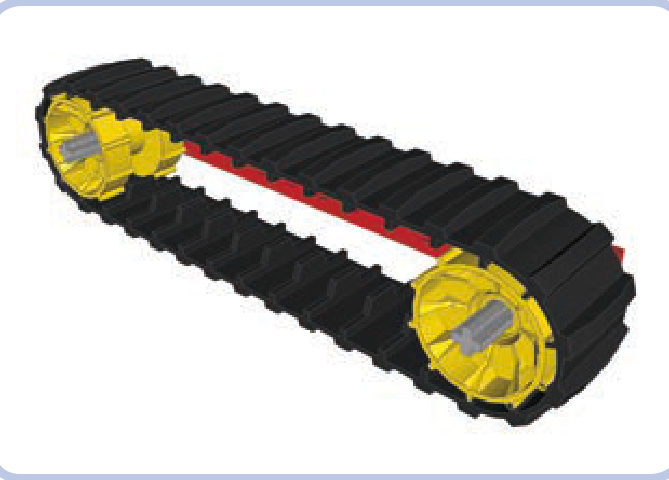
Figure 16-1: A large Technic tread and two Technic tread hubs
This track has 34 segments and is a little less than 3 studs wide. With its deep tread, the rubber provides excellent traction. The loop must be driven with a special type
of sprocket wheel called a tread hub; the track requires two hubs 13 studs apart to be fully stretched, as shown in Figure 16-1. Tread hubs have a diameter of 3 studs, and their width is just a little bit less. They come in a variety of colors, and they use pin holes. In order to make your sprocket gears rotate with an axle, you must lock them with 16-tooth gears, as shown in Figure 16-2. You’ll need two 16-tooth gears per hub—one on each side—or, to save space, you can use a single gear on one side and a bush on the other.
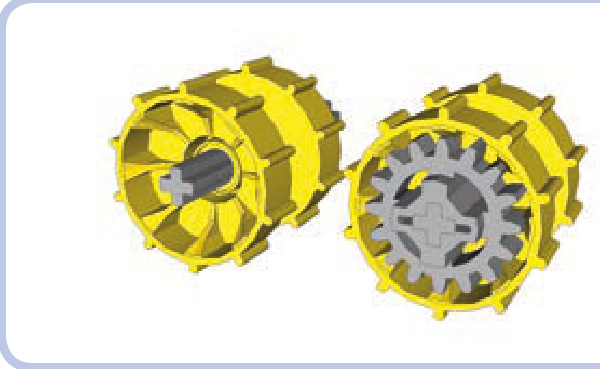
Figure 16-2: Two tread hubs: one empty (left) and one with a 16-tooth gear inserted (right). Since the hub is less than 3 studs wide, the gear sticks out slightly.
Advantages of rubber tracks:
They are a single, unbreakable loop.
They provide superb traction.
They create minimal noise when driving.
Disadvantages of rubber tracks:
Their length is limited and fixed.
Their sprocket wheels are available in only one size.
Rubber becomes less and less elastic over time.
hard plastic tracks
Hard plastic tracks (also known as solid tracks) are individual plastic links connected with one another. Their length can be easily adjusted, and they come in two versions: an older (and smaller) one and a newer (and bigger) one, both shown in Figure 16-3. Figure 16-4 shows a vehicle using the new plastic track type.
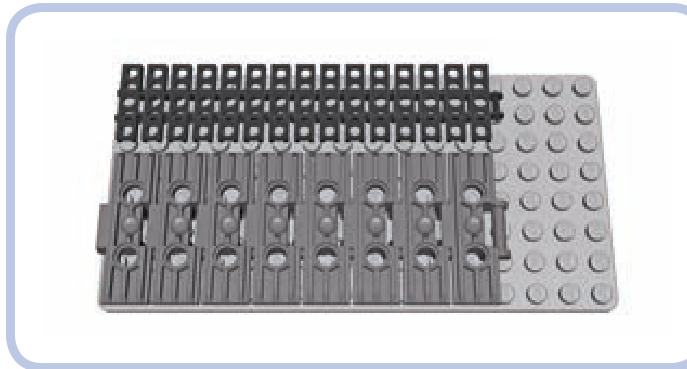
Figure 16-3: The older 15-link-long track and the newer 8-link-long track are both 13 studs long.
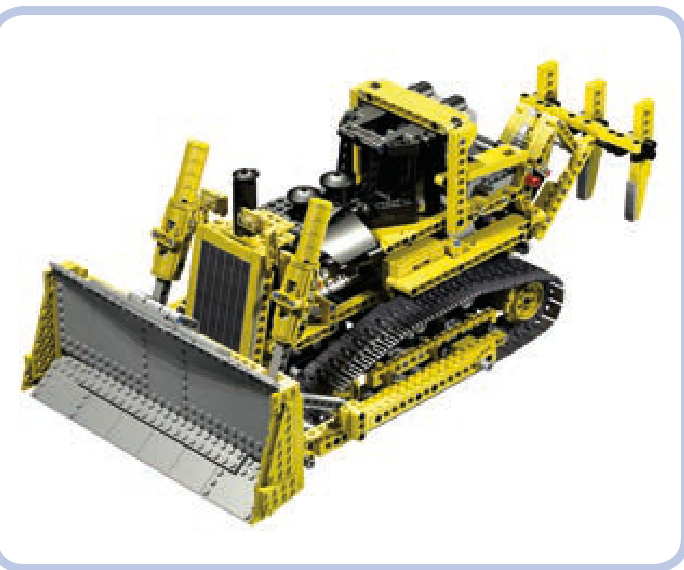
Figure 16-4: The newer type of solid track was introduced in the famous 8275 set.
Neither type of hard plastic track measures a whole number of studs in width. Instead, the tracks are slightly narrower, which prevents them from abrading the structure around them as they rotate. The older tread type is slightly less than 3 studs wide, and the newer one is slightly less than 5 studs wide. The length of tracks is a little difficult to compare, as no link is an equal number of studs long either; however, a 15-link-long section of older track is equal to an 8-link-long section of new track, and those lengths are both equal to 13 studs, as shown in Figure 16-3. A single link of the newer type is thus equal to 1.875 links of the older type. A link of the new track is 1.625 studs long, while the older lin is 0.867 studs long.
The older tracks come primarily in black, and they are similar in construction to LEGO chains, as you can see from their links in Figure 16-5. This means that any gear that works well with a chain can be our sprocket wheel for a tracked vehicle. As shown in Figure 16-6, a single link occupies two teeth on a gear.
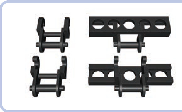
Figure 16-5: Regular LEGO chain links (left) and older-type track links (right). The older track links are just modified chain links.
Figure 16-6: A section of older track wrapped around a 16-tooth gear
Five types of gears can be used as sprocket wheels for the older tracks (see Figure 6-5 on page 58). Other gears just aren’t suitable because of the shape of their teeth or simply because of their small diameter.
The small openings in the older tracks can hold a plate, a tile (as shown in Figure 16-7), or even a brick that is at least 4 studs long. While bricks aren’t typically used because they fall off too easily, plates and tiles can make the tracks wider and improve their appearance.
Figure 16-7: A section of older track with tiles added. Note that only every other link can have a piece inserted into it.
Figure 16-8 shows my model of a Liebherr R944C excavator, which combined two types of gears to keep the tracks in place. I used 24-tooth gears at the ends of the tracks and 16-tooth gears to give shape to the tracks’ upper sections.
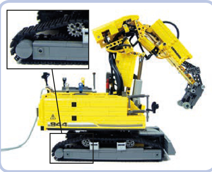
Figure 16-8: A model of a Liebherr R944C, using two types of gears
The newer tracks are made of massive links that come primarily in dark grey; black and metallic silver versions are available as well. Each link comes with two pin holes, which allow for modification (see Figure 16-9).
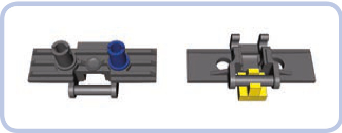
Figure 16-9: Adding a pin to a track allows us to attach bricks or tiles
The new solid tracks can’t be driven by regular Technic gears; instead, they use special sprocket wheels. There are two options: a big wheel and a small one (both shown in Figure 16-10). The big sprocket wheel can have up to 10 links wrapped around it, is almost 2 studs thick, and comes primarily in yellow, with orange and black available, too. The small one can have up to 6 links wrapped around it, is 1 stud thick, and comes in black and pearl grey.
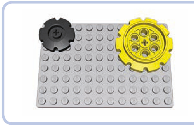
Figure 16-10: Sprocket wheels for the newer track type
The pin holes on top of the newer links can be used to attach Technic bricks (as shown in Figure 16-11) or beams (as shown in Figure 16-12) to them, making them wider and suitable for driving in snow. Both bricks and beams can be attached to every link using two half or three-quarter pins, with the latter ones being less likely to fall off. It is also possible to weave a regular rubber band into the pin holes, improving the traction of the tracks and reducing the noise they create while driving.
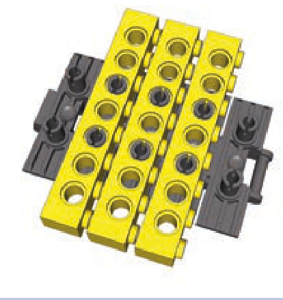
Figure 16-11: Section of the newer track with bricks attached
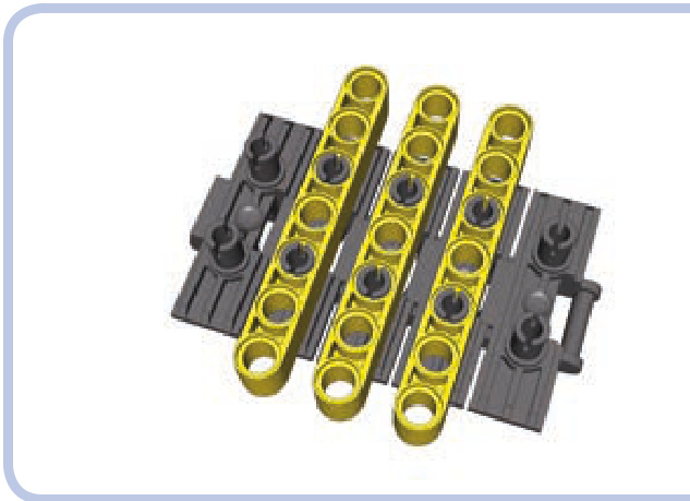
Figure 16-12: Section of the newer track with beams attached
The two solid track types differ in how much they can be stretched; the older type is more elastic but, at the same time, more fragile and prone to break. The newer type is much sturdier but very rigid, and as a result, it’s difficult to obtain optimum tension with it. If your tread is too loose or too tight, it will affect how a vehicle drives. The rule of the thumb is to tighten it as much as possible and then give it at least half of a link of play.
Advantages of solid tracks:
N Their length is adjustable.
N They look more realistic than rubber tracks.
They can be driven by a wider selection of sprocket wheels.
Disadvantages of solid tracks:
They have poor traction.
They’re prone to coming apart (especially the older type).
It’s difficult to obtain optimum tension (especially with the newer type).
They’re noisy while driving (especially the newer type).
tracked wheel systems
Tracks greatly improve a vehicle’s off-road performance, especially on mud, snow, or other unreliable surfaces. But how well a vehicle moves on its tracks depends largely on its wheels.
Strange as it may seem, wheels are no less important for tracked vehicles than they are for a car or truck. Firstly, they provide power to the tracks and keep them from falling off. Secondly, they can be suspended in order to improve the flotation of the vehicle, which describes how well the suspension handles obstacles. A suspension that adapts well to rough terrain provides good flotation, reducing the shock transferred to the vehicle as it moves.
Not e The first tanks ever built provide a good example of just how important suspension is. Because these tanks lacked any kind of suspension, the crewmen of such tanks would often be knocked unconscious by shocks while traversing trenches.
Let’s discuss the basic wheel systems. The simplest wheel system consists of two sprocket wheels per track, as shown in Figure 16-13. Usually about half of such a wheel comes in contact with the track, more than any other wheel in the system—which is why it’s important that these wheels are those that drive the tracks. Usually only one sprocket

Figure 16-13: A track with two sprocket wheels: an idle one (grey) and a driven one (red)
wheel is actually driven, and it’s often the rear one because it’s convenient to have propulsion systems at the back of the vehicle. But it doesn’t really matter which sprocket wheel is driven, as the track works like a chain and transfers the drive to the other wheel.
The second function of the sprocket wheels is to maintain the track’s tension, which is particularly important as the vehicle moves over obstacles. Sprocket wheels can be suspended on an elastic element to maintain this tension. A loss of tension can cause the track to slip or even separate.
But with the basic two-wheel-per-track system, it would be difficult to add any suspension. We could suspend the nondriven sprocket relatively easily, but suspending the driven one would be much more challenging. This is why road wheels were invented.
A more advanced wheel system includes road wheels at the bottom of the vehicle (shown in blue in Figure 16-14). Road wheels can be used in any number, they are not driven, and they can be easily suspended. They are usually located closer to the ground than sprocket wheels, and they support the weight of the vehicle. Some vehicles come with sprocket and road wheels on the same level, making the road wheels difficult to suspend but increasing the total area of contact between the track and the terrain. Real tracked vehicles have been built both with many small road wheels (as shown in Figure 16-15) or with a few big ones. As a kind of compromise between the two extremes, modern tanks usually have six or seven road wheels per track that are just over half as big as the sprocket wheels.
The most complex wheel systems also include return rollers (shown in yellow in Figure 16-16). They are neither driven nor suspended, and their only function is to support the upper portion of the track. Return rollers can have minimal contact with the track and, in fact, don’t even have to rotate—it’s enough if the track can slide over them. As tracks are always more or less loose, vehicles with long tracks usually need at least two return rollers. It is also possible to use road wheels large enough to function as return rollers, as shown in Figure 16-17.
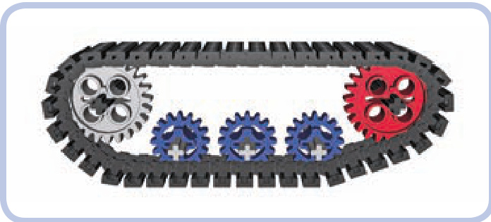
Figure 16-14: A track with two sprocket wheels and three road wheels
Figure 16-15: With 11 road wheels per track, the British Churchill tank is an extreme example of using a design that includes many small road wheels.
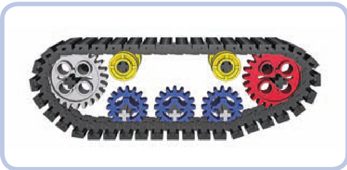
Figure 16-16: A track with two sprocket wheels, three road wheels, and two return rollers
Figure 16-17: Soviet tanks from the World War II era—such as this T34— used road wheels so big that they had contact with both the lower and upper portion of the track, thus eliminating the need for return rollers.
A good example of a modern wheel system is the one used on the classic Sherman tank. It includes two large sprocket wheels, six smaller road wheels, and two return rollers per track (see Figure 16-18). Note that the forward sprocket is driven and the rear one is idle.
Figure 16-18: The classic Sherman tank used a wheel system that included return rollers.
Now that you know what types of wheels are used in tracked vehicles, we can move on to the suspension systems.
suspension systems
The primary function of a suspension system is to increase stability and reduce the shock transferred to the vehicle. Its secondary function is to prevent the tracks from falling off. A suspension system achieves this function by keeping road wheels in close contact with the tracks regardless of the shape of the ground. The vast majority of tracked vehicles have suspension only on the road wheels, largely for simplicity’s sake. All the suspension systems described below are designed for road wheels but can be used with sprocket wheels as well.
Not e The type of LEGO track you use doesn’t affect the suspension; it only determines the type of sprocket wheels you can use. The examples of suspensions in this chapter show variants for both LEGO track types to demonstrate how a given suspension works with various wheels.
bogies
A bogie is the simplest type of tracked suspension. It is simply a beam that has one road wheel on either end; this beam freely rotates around a central axle connected to the vehicle, as shown in Figure 16-19. As the road wheels on the bogie go up and down, only half of their travel is transferred to the bogie’s central axle—for example, when a wheel moves upward by 2 studs, the axle will only move upward by 1, as shown in Figure 16-20. So bogies provide reasonably good flotation, but they don’t reduce shock.
Figure 16-19: The yellow beam rotates around the central pin, creating a bogie with two road wheels.
Figure 16-20: In this example, one road wheel is raised by 2 studs, but the bogie’s central axle (and thus the vehicle) is raised only by 1 stud.
Not e The basic principle of bogies is that only 50 percent of the road wheels’ vertical travel is transferred to the vehicle. But note that this principle is true only if the obstacle is shorter than the length of the entire bogie— that is, shorter than the span of two road wheels.
Figure 16-21 shows an example of a bogie for the newer LEGO track type. The newer tracks are larger and usually used with larger and heavier vehicles, which is why this bogie variant is reinforced on the front and back sides (and is therefore sturdier).
Figure 16-21: A reinforced bogie for the new LEGO track type
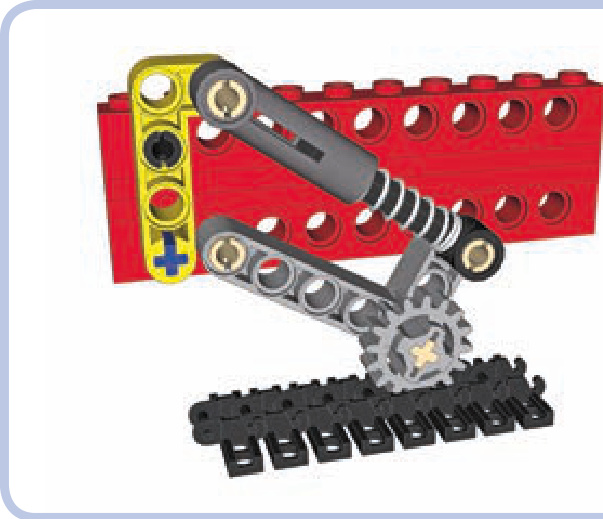
Figure 16-22: A simple trailing arm with a shock absorber
trailing arms suspension with shock absorbers
Trailing arms are used in more advanced suspension systems, where each road wheel is located on the end of an arm and supported against the weight of the vehicle by a shock absorber (or another elastic element), as shown in Figure 16-22. As most tracked vehicles usually have relatively low profiles, 6.5L shock absorbers are better suited to most tracked vehicles than their longer variants.
Trailing arm suspensions are sensitive to the direction of the tracks’ rotation, and tracks always rotate more freely in one direction than the reverse. The arms are located in front of the road wheel.
There are a number of possible variants for this sus pension system, depending on how much load each road wheel has to handle, how much space you can use, and what suspension travel and hardness you want to achieve. Figures 16-22 through 16-24 show some common variations.
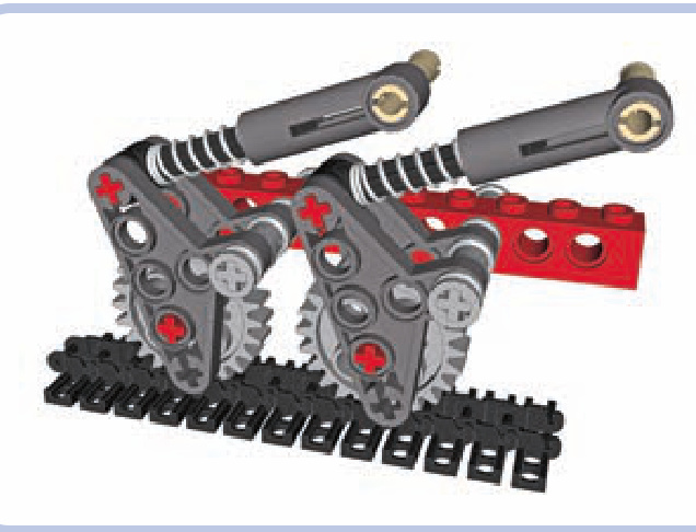
Figure 16-23: A more complex trailing arm system that works with 24-tooth gears
Not e The first and last road wheels in a track usually handle more load than the middle ones. It is therefore a good idea to use harder shock absorbers for these wheels than for the middle wheels. The weight distribution of the vehicle (front-heavy, center-heavy, or rear-heavy) should also be considered.
The setup in Figure 16-23 works only with 24-tooth gears and isn’t that soft but takes little vertical space, which is helpful when you need the road wheels to be very close to each other.
Figure 16-24 shows another compact setup that works with all types of wheels, including those for the newer track system. It allows a lower overall profile, but it needs the road wheels to be spaced farther apart.
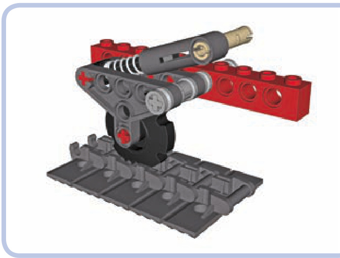
Figure 16-24: Another compact trailing-arm setup
trailing arm suspensions with torsion bars
Shock absorbers are efficient but large; their length can force us to build our vehicles taller than we would otherwise need to. Thankfully, there’s a very attractive alternative when building a trailing arm suspension: torsion bars.
A torsion bar is a long, slightly elastic element, positioned perpendicular to a vehicle’s hull. One end of the bar is locked to the chassis so that it can’t rotate. The other end is attached to a trailing arm with a road wheel on the other end, and it rotates together with the arm. So as the road wheel goes up, the arm twists the bar around its axis, as shown in Figure 16-25. And the great news is that all LEGO axles (except for the very short ones) are elastic enough to function as torsion bars.
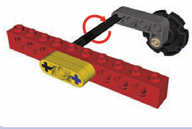
Figure 16-25: The basic scheme of a torsion bar
In the figure, the black 8L axle is functioning as a torsion bar; its one end is locked into the chassis (represented by the red brick), and its other end is locked into the trailing arm (represented by the dark grey beam). Now, if the road wheel at the end of the arm meets an obstacle that makes it go up, the trailing arm will oscillate around the axle, making it twist a little. Once the obstacle is passed, the axle will untwist, returning the arm and the wheel to the initial position. Of course, in a real vehicle the torsion bar needs to be supported.
Figure 16-26 shows a more complex example of the torsion-bar suspension in action, including such a support. Note that the 8L axles go through two bricks, but they are locked only with the one closer to the middle of the hull. They can freely rotate inside the outer brick, which is used only to support them.
Figure 16-26: A more complex torsion-bar suspension
The torsion-bar suspension requires only common pieces, and its hardness can be adjusted by using shorter or longer axles or by simply changing the point at which the axles are locked to the chassis (the closer to the trailing arm, the harder the suspension). Twisting LEGO axles may seem risky, but they are surprisingly resistant to damage. I have used 8L axles as torsion bars in a model with a total weight of around , where each torsion bar handled an average load of almost and a much greater load when negotiating obstacles. Even after the model went through a lot of tests on rough terrain, the axles were in pristine condition.
This kind of suspension, unlike shock absorbers, also has the advantage of using minimal space inside the tracks. Its disadvantages are that it takes 1 stud of vertical space at the bottom of the hull (as shown in Figure 16-27) and that this space is so densely filled with axles that it’s usually impossible to use it for anything else. A torsion-bar suspension also doesn’t work well for lightweight models. If the average load per road wheel is less than 100 grams, the effect of this suspension is barely noticeable.
相关页面
图片总数:188 张