乐高零件标签系统
作者与版本
- 作者:Tom Alphin
- 版本:39.2
- 发布日期:2023年1月9日
- 官方网站:https://brickarchitect.com/labels/
概述
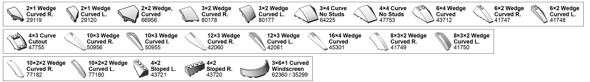
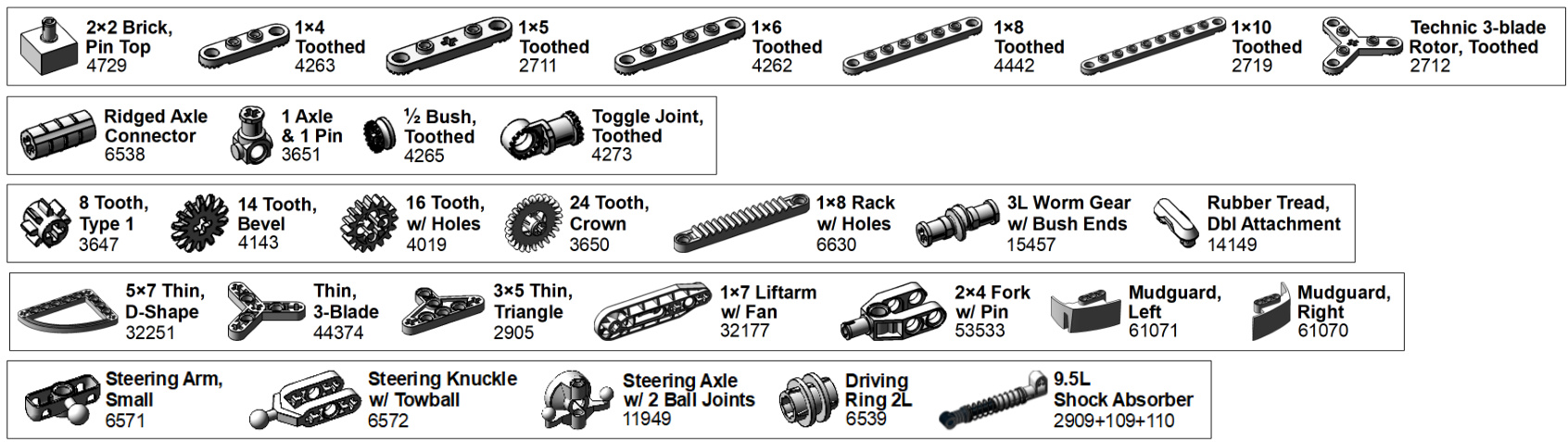
这是一套完整的乐高零件分类标签系统,帮助乐高爱好者整理和识别各类零件。系统包含了基础砖、墙面零件、SNOT技术零件、夹子、铰链、斜坡、曲面零件、车辆零件、人仔、自然元素和科技件等全部类别。
1.BASIC
LEGO Brick Labels by Tom Alphin.
Version 39.2, January 9,2023.
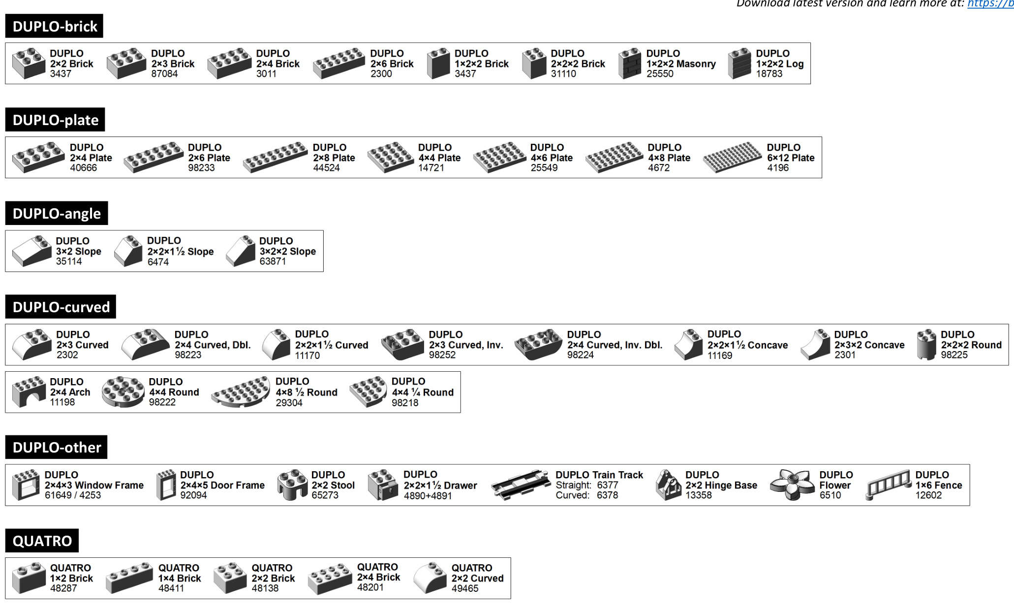
Download latest version and learn more at:https://brickarchitect.com/labels/
2.WALL
WALL-window_door
3.SNOT
4. CLIP
CLIP-clip
CLIP-flag
5.HINGE
6. SOCKET
7. ANGLE (1/2)
ANGLE-slope_10_18_30

ANGLE-slope_33


ANGLE-slope_55_65_75

ANGLE-slope_inverted
ANGLE-windscreen
7. ANGLE (2/2)

8. CURVED(1/3)
8. CURVED (2/3)

CURVED-curved
8. CURVED (3/3)
CURVED-wedge
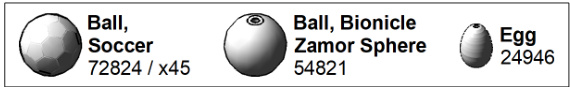
CURVED-ball
CURVED-heart_star

CURVED-other

9.VEHICLE (1/3)
VEHICLE-wheel_integrated_tire

VEHICLE-wheel_8mm

VEHICLE-wheel_11mm

VEHICLE-wheel_14mm_15mm

VEHICLE-wheel_18mm

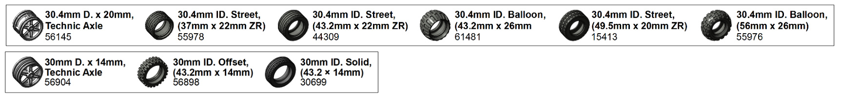
VEHICLE-wheel_30.4mm
9. VEHICLE (2/3)
VEHICLE-wheel_43.2mm

VEHICLE-wheel_56mm

VEHICLE-wheel_motorcycle

75mm D. x 17mm, Technic Axle 88517

75mm ID. Racing, (94.2mm x 22mm) 88516
VEHICLE-pin_technic

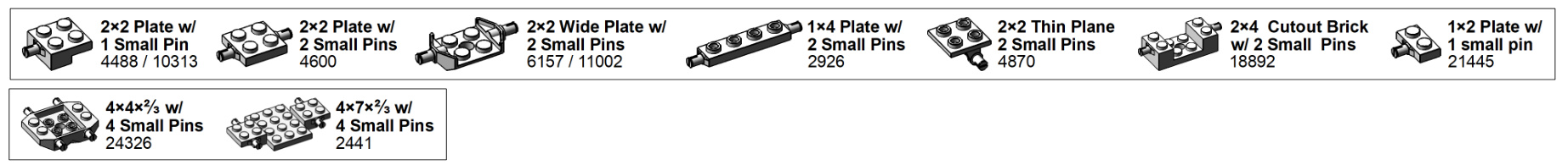
VEHICLE-bracket

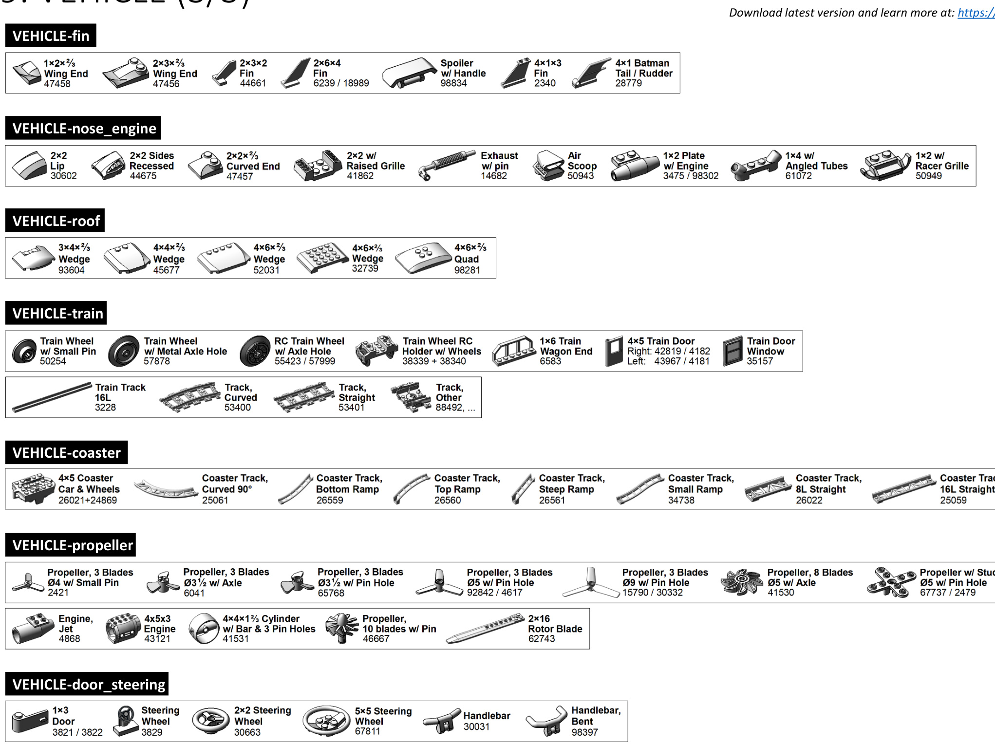
9.VEHICLE (3/3)
10. MINIFIG (1/3)
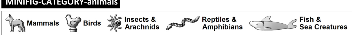
MINIFIG-CATEGORY-clothing_hair


MINIFIG-minidoll
| Mini-doll Head 92198/... | Mini-doll Torso 92241/... | 司 | Mini-doll Pants 92251/... | U Mini-doll Dress/Skirt 92252/... |
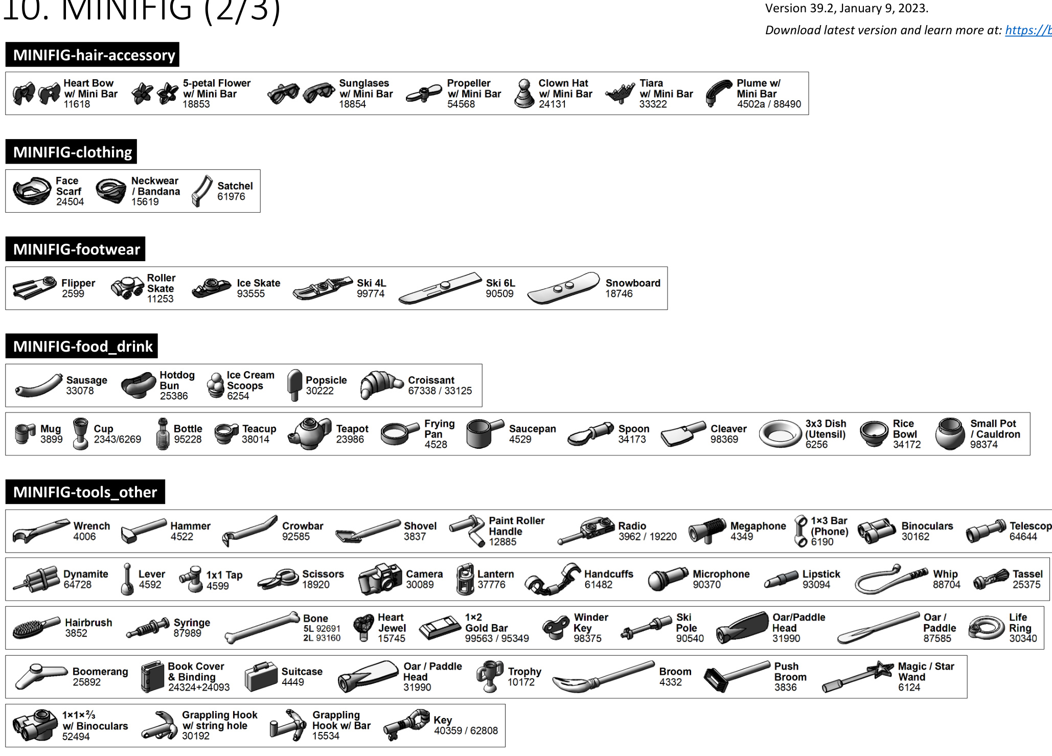
10. MINIFIG (3/3)
11.NATURE
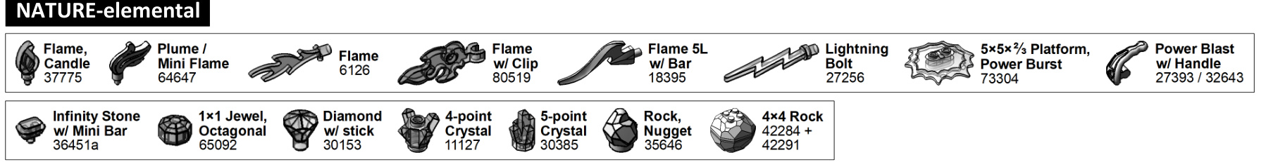
NATURE-flower

NATURE-plant

NATURE-produce

NATURE-barb_horn_tail
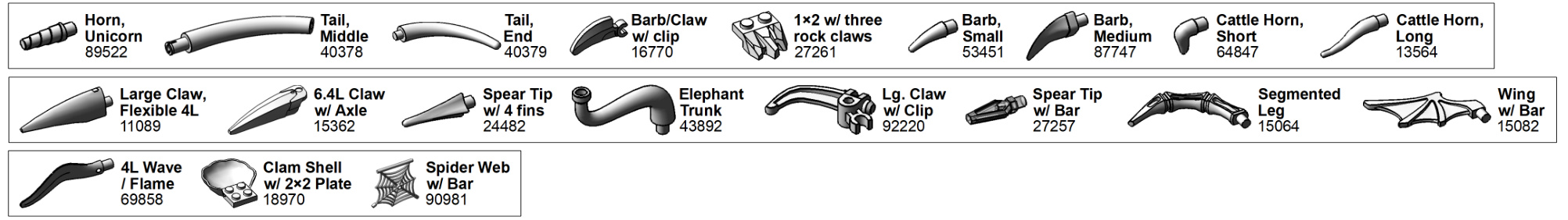
NATURE-tooth

12. TECHNIC (1/4)
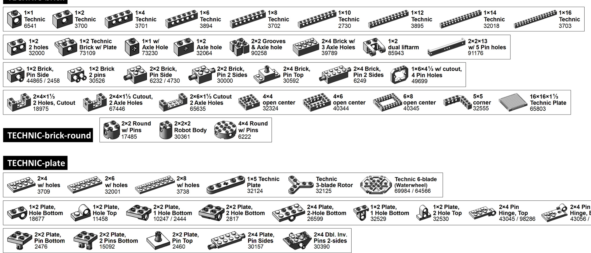
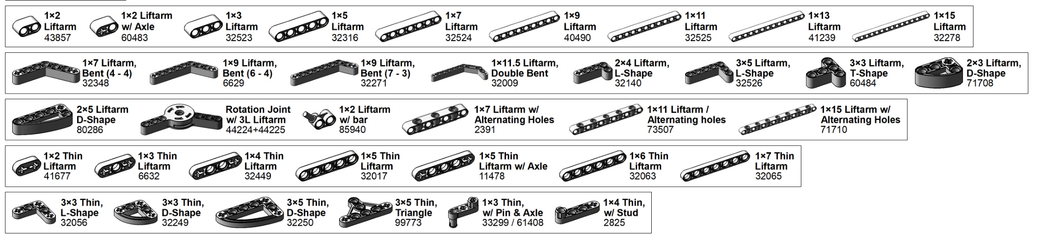
12. TECHNIC (2/4)

TECHNIC-panel
TECHNIC-axle

12. TECHNIC (3/4)
12. TECHNIC (4/4)
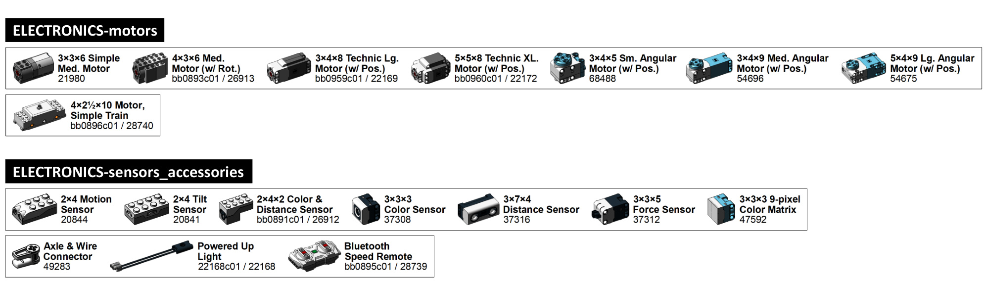
13.ELECTRONICS


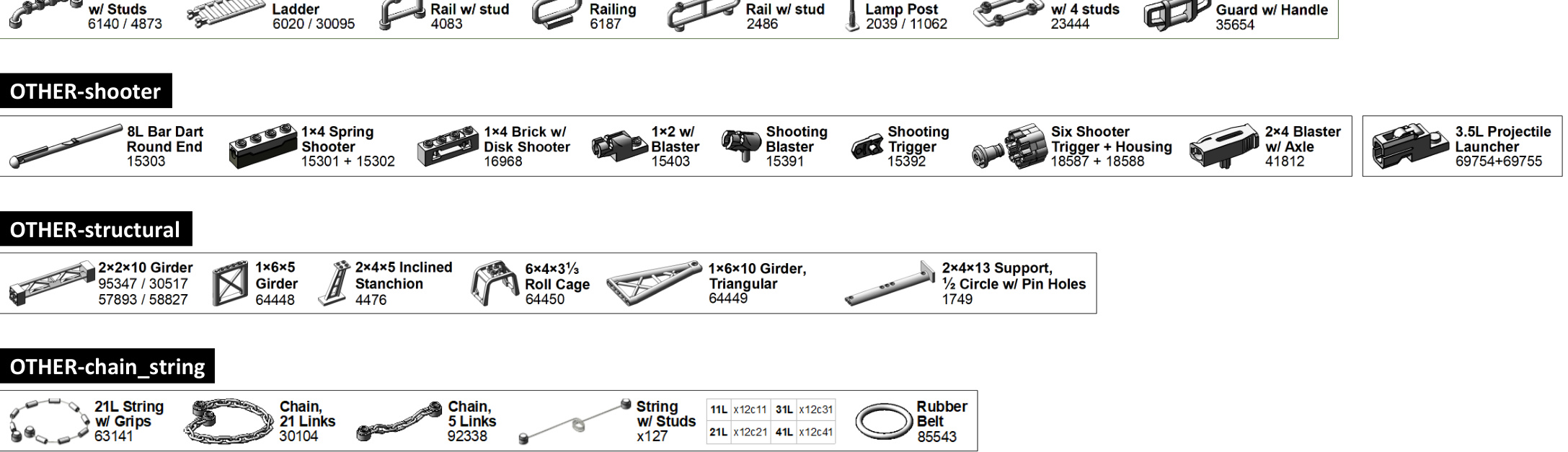
14.OTHER

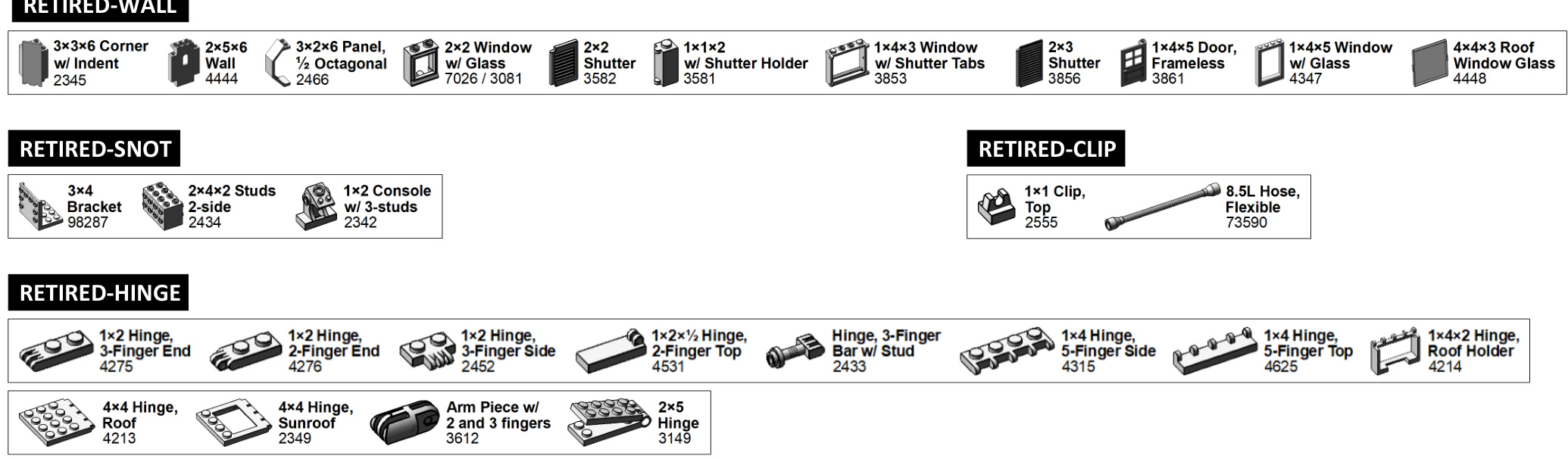
15. RETIRED (1/2)

RETIRED-SOCKET-click

RETIRED-ANGLE

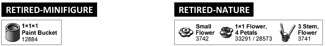
15. RETIRED (2/2)

RETIRED-VEHICLE

RETIRED-TECHNIC
RETIRED-ELECTRONICS


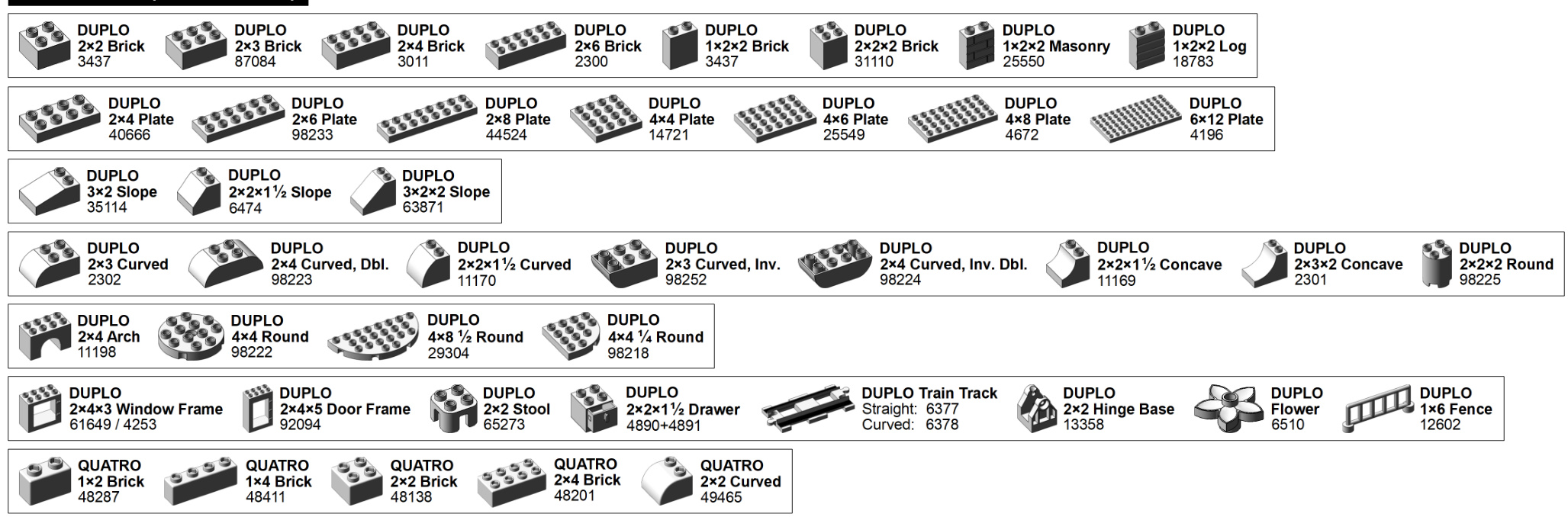
16.DUPLO
LEGO Brick Labels - Version 39
LEGO Brick Labels - Version 39

LEGO Brick Labels - Version 39
NEW IN v39 (DUPLO Parts)
TIne unofficial ? LEGO BUILDER’S GUIDE
ADVANCE PRAISE FOR THE UNOFFICIAL LEGO BUILDER’S GUIDE
“Brilliant! Bedford guides you step-by-step through the wonderful, limitless LEGO system using his uniquely engaging writing style and passion for the brick. A must-read for every LEGO builder.”
–TIM COURTNEY, LDRAW.ORG, CO-AUTHOR OF VIRTUAL LEGO “The Unofficial LEGO Builder’s Guide is an excellent resource for both the beginner and the expert LEGO builder. For the beginner, it’s a great introduction to the hobby and reference to many of the building tricks that the advanced builders use. For the expert, it’s a great reference for methods and approaches to building in new themes and scales. I recommend it highly for anyone who is interested in LEGO building.”
–JOE MENO, EDITOR IN CHIEF, BRICKJOURNAL “This is the book I wished I had as a kid and as an adult returning to the hobby. It’s a great resource, and is going to have a cherished place on my work table for the foreseeable future.”
–JACOB H. MCKEE, LEGO COMMUNITY DEVELOPMENT MANAGER FOR NORTH AMERICA, AUTHOR OF GETTING STARTED WITH LEGO TRAINS
“The Unofficial LEGO Builder’s Guide should be considered the benchmark on all aspects of the LEGO building hobby. A ‘must-have’ for those who are just starting to experiment with LEGO and experts looking for areas to expand.”
–KIETH JOHNSON, AEROSPACE ENGINEER, UNITED SPACE ALLIANCE “The Unofficial LEGO Builder’s Guide will make for a great beginning for any future architects or LEGO hobbyists. The detailed model instructions not only show how to build the example models, they also inspire you to go further and build anything you can think of, the only limit being your imagination.”
–GARY ISTOK, LEGO BUILDER, COLLECTOR, AND HISTORIAN “The Unofficial LEGO Builder’s Guide is a great tool for both young and old. It explains in clear and concise language the things you will need to know to get started and develop your skills as a LEGO builder. From the different types of building techniques and styles, to a comprehensive guide of important parts, this is a great springboard to unleashing the inner Master Model Builder that is in us all!”
–BILL VOLLBRECHT, FORMER MASTER MODEL BUILDER FOR LEGOLAND CALIFORNIA AND OWNER OF WWW.BRICKCREATIONS.COM
How many things are waiting to be created?
THE UNOFFICIAL LEGO® BUILDER’S GUIDE
by Allan Bedford

San Francisco
THE UNOFFICIAL LEGO® BUILDER’S GUIDE. Copyright 2005 by Allan Bedford.
All rights reserved. No part of this work may be reproduced or transmitted in any form or by any means, electronic or mechanical, including photocopying, recording, or by any information storage or retrieval system, without the prior written permission of the copyright owner and the publisher.
Printed on recycled paper in the United States of America
1 2 3 4 5 6 7 8 9 10 – 07 06 05 04
No Starch Press and the No Starch Press logo are registered trademarks of No Starch Press, Inc. Other product and company names mentioned herein may be the trademarks of their respective owners. Rather than use a trademark symbol with every occurrence of a trademarked name, we are using the names only in an editorial fashion and to the benefit of the trademark owner, with no intention of infringement of the trademark.
Publisher: William Pollock
Production Manager: Susan Berge
Cover and Interior Design: Octopod Studios
Developmental Editors: William Pollock, Peter Spear
Copyeditor: Rebecca C. Rider
Compositor: Riley Hoffman
Proofreader: Stephanie Provines
For information on book distributors or translations, please contact No Starch Press, Inc. directly:
No Starch Press, Inc.
555 De Haro Street, Suite 250, San Francisco, CA 94107
phone: 415.863.9900; fax: 415.863.9950; info@nostarch.com; http://www.nostarch.com
The information in this book is distributed on an “As Is” basis, without warranty. While every precaution has been taken in the preparation of this work, neither the author nor No Starch Press, Inc. shall have any liability to any person or entity with respect to any loss or damage caused or alleged to be caused directly or indirectly by the information contained in it.
Librar y of Congress Cataloging-in-Publication Data
Bedford, Allan. The unofficial LEGO builder’s guide / Allan Bedford. p. cm. Includes index. ISBN 1-59327-054-2
- LEGO toys. I. Title. TS2301.T7B44 2005 688.7’25—dc22
To my wife Kathie and our little family. For believing that I could do this.
Creativity is just having enough dots to connect. —Steve Jobs
B R I E F C O N T E N T S
Acknowledgments . .xv
Introduction . . xvii
Chapter 1: The LEGO System: Endless Possibilities .
Chapter 2: Back to Basics: Tips and Techniques… .19
Chapter 3: Minifig Scale: Oh, What a Wonderful Minifig World It Is!.. .37
Chapter 4: Miniland Scale: The Whole World in Miniature.. .63
Chapter 5: Jumbo Elements: Building Bigger Bricks .81
Chapter 6: Microscale Building: More Than Meets the Eye. .99
Chapter 7: Sculptures: The Shape of Things to Build . .115
Chapter 8: Mosaics: Patterns and Pictures in Bricks . .133
Chapter 9: Technic: Not as Technical as It May Seem … .153
Chapter 10: Putting It All Together: Where Ideas Meet Bricks . .173
Chapter 11: Beyond Just Bricks: Other Things to Do Besides Building .195
Chapter 12: Sorting, Storage, and Sitting Down to Build Something. .209
Chapter 13: Making and Using Tools for LEGO Projects .. .227
Appendix A: Brickopedia.. .239
Appendix B: Design Grids: Building Better by Planning Ahead .299
Index . .311
C O N T E N T S I N D E T A I L
ACKNOWLEDGMENTS
INTRODUCTION xvii
1 THE LEGO SYSTEM: ENDLESS POSSIBILITIES 1
A Brick Vocabulary 2
Sizing Up the Elements 2
The Stud . 3
The Tube 4
The Brick 5
The Plate . 6
The Slope 7
Specialized Elements . 8
Technic 9
Arch Pieces 9
Tiles and Panels 10
Cylinders and Cones 11
Baseplates 12
Decorative Elements 12
Precision, Geometry, and Color 13
Why Precision Manufacturing Matters 13
Fun with LEGO Geometry 13
The Colors 15
Review: The LEGO System … 17
2 BACK TO BASICS: TIPS AND TECHNIQUES 19
Decisions, Decisions: The Best Ways to Connect Bricks 20
Stacking . 21
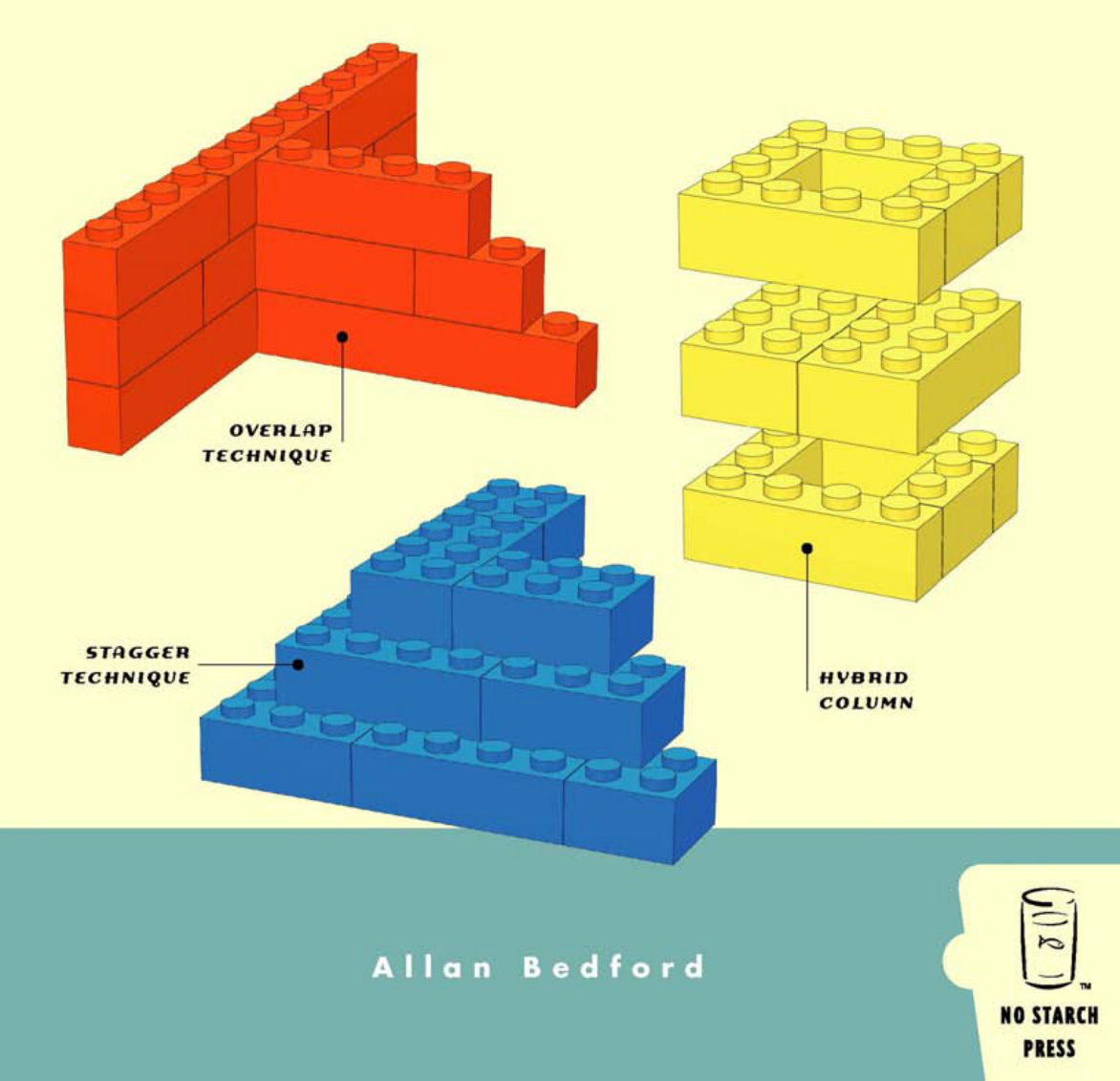
Overlapping 22
Staggering 24
Building Walls 25
Connecting Walls 25
Straight Bricks Can Make Round Walls 27
Bracing: Unseen but Not Forgotten 29
Bracing Beams Columns … 29
Beams 30
Columns 32
Review: Basic Building Principles 35
- Build big but think small. 35
- Pick the right bonding pattern. 35
3 MINIFIG SCALE: OH, WHAT A WONDERFUL MINIFIG WORLD IT IS!
Scale: It’s All Relative 38
Calculating Scale 38
From the Ground Up: Creating a Minifig-Scale Building 40
Building Two Versions of the Train Station 40
Bill of Materials: The Parts You’ll Need to Make This Model 41
Step by Step: Train Station Construction Details 41
Submodel: The Train Station Roof 51
Substitution: When Other Parts Will Do 54
Substitute Walls 55
Substitute Arches 55
Substitute Windows . 56
Substitute Roofs 57
Review: Building Techniques and Alternatives 61
4 MINILAND SCALE: THE WHOLE WORLD IN MINIATURE 63
Miniland Scale: Bigger but Still Small 64
Creating a Basic Miniland Figure 65
The Best Bits: Useful Pieces for Miniland People 66
Basic Miniland Figure 68
Mix-and-Match Parts 69
On The Run: Making Miniland Figures Come to Life 73
Miniland Buildings 75
Creating a Scene: Combining Figures and Buildings 75
Street Life: A Simple Downtown Scene in Miniland Scale 76
Behind the Scenes 79
Review: Miniland Scale, Big Possibilities 80
5 JUMBO ELEMENTS: BUILDING BIGGER BRICKS 81
Scaling Up: How It’s Done 84
The Walls Are Closing In! 87
Other Parts, Same Technique 89
Building with Jumbo Bricks 92
Other Scales: What Scales Work, and Why 94
Picking the Right Scale . 95
Approximation 96
Review: Jumbo Bricks Are Just the Start 98
6 MICROSCALE BUILDING: MORE THAN MEETS THE EYE 99
Microscale: Small Scale with Big Possibilities . 101
Getting Started: Ignore the Details 102
x Con t en ts in Det ai l
Translating Ideas into Bricks 105
Recap the Technique 107
How Do I Know What Scale I’m Using? 107
Decide on a scale before you begin building. 107
Figure out the scale after you’re done building. 108
Replacing Full-Size Parts with Microscale Stand-Ins 108
Microscale Wheels 109
Microscale Windows . 109
Instructions for Microscale House 110
Recap of Replacement Parts 113
Review and Suggested Subject Matter 113
7 SCULPTURES: THE SHAPE OF THINGS TO BUILD 115
Spheres: Round and Round They Go 116
Divide and Build: Two Sections Means Twice the Fun 118
Beyond Spheres: Sculpting Other Subjects 126
Choosing a Subject 126
Getting Started on the Sphinx 127
Analyzing the Angles: Building the Head 127
Special Features: Special Techniques 128
Building the Foundation Last … 131
Review: Sculptures—In the Eye of the Builder 132
MOSAICS: PATTERNS AND PICTURES IN BRICKS 133
Two Types of Mosaics 133
What Can You Do with Mosaics? 135
How Big Should a Mosaic Be? . 135
What You Need to Make a Mosaic 135
Designing a Studs-Out Mosaic 136
Geometric Patterns 136
Copies of Pictures .. 140
Designing a Studs-Up Mosaic 146
Design Grids for the Studs-Up Technique 147
Mosaics on Edge 148
Review: Mosaics of All Sizes and Shapes 150
TECHNIC: NOT AS TECHNICAL AS IT MAY SEEM 153
Technic: A System Within a System 155
Technic Pieces: An Overview 155
Bricks 156
Studless Beams and Lift Arms 157
Gears 158
Pins/Axles 158
Bushings 159
Couplers 159
Getting Started with Technic: Assembly Notes 160
Gear Trains 160
Going Vertical 164
Technic Meets Basic Elements 165
Putting It All Together: Building a Technic Model 168
Review: What Is Technic? 171
10PUTTING IT ALL TOGETHER:WHERE IDEAS MEET BRICKS
173
Thinking Like a Model Designer 173
Limit Your Scope 174
Getting Started: Pick Your Subject 175
Work from the Bottom Up 176
Let Reality Guide Your Design Decisions . 179
A Different Perspective .. 180
Pick a Scale, Any Scale 181
Color Concerns . 181
Elements of Design 182
Bringing It All Together: The Final Design 185
Step by Step: Shuttle Construction Details 187
Something’s Wrong: Redesigning Doesn’t Mean You’ve Failed 193
After You’re Done 193
Review: Taking On the Role of Model Designer 194
11 BEYOND JUST BRICKS: OTHER THINGS TO DO BESIDES BUILDING 195
“I Give It a Nine Out of Ten”: Writing Reviews of LEGO Sets 196
A Simple Review … 196
Sharing Your Review 198
How It’s Made: Creating Instructions for Your LEGO Models 198
Step-by-Step Pictures 199
Computer-Assisted Instructions . 200
Having Fun: Making and Playing Games with LEGO Pieces 201
Games You Already Know 201
Original Games . 203
An Example of an Original Game: Connect-Across (Basic Rules) 204
Designing Your Own Game 207
Review: Enjoying Every Aspect of LEGO 207
12 SORTING, STORAGE, AND SITTING DOWN TO BUILD SOMETHING
Sorting vs. Storing: What’s the Difference? 210
Sorting Bricks: Divide and Conquer 211
Small-Sized Collections 212
Medium-Sized Collections 212
Large-Sized Collections 214
Storing Bricks 216
Start Small, Keep It Simple 217
Containers with Compartments 218
Shoeboxes: Not Just for Shoes Anymore .. 219
Keeping Track of the Little Pieces: Tackle Boxes to the Rescue . 221
Reuse Containers You May Already Have: Tubs and Buckets .. 221
Deep Storage: Taking Care of Larger Quantities .. 223
Setting Up a Building Area 223
Review: Unique Solutions for Every Builder 226
13 MAKING AND USING TOOLS FOR LEGO PROJECTS 227
Presser Tool 229
The Ruler 230
Pin Stand Tool 231
Brick Separator 233
Non-LEGO Tools 236
Other Useful Items 237
Review: The Right Tools for the Job 238
A BRICKOPEDIA
239
Brickopedia Breakdown 240
Review: Bricks, Plates, and So Much More 298
DESIGN GRIDS: BUILDING BETTER BY PLANNING AHEAD 299
Downloading the Grids 299
About the Grids 300
Design Grid #1 300
Design Grid #2 300
Design Grid #3 301
Design Grid #4 303
Using the Grids Effectively 303
Same Model, Different Views 304
Sketching or Planning 304
Description and Date for Future Reference 304
Drawing on Grid #1 305
Drawing on Grid #2 308
Drawing on Grid #3 308
Drawing on Grid #4 310
Review: From Grids to Bricks 310
A C K N O W L E D G M E N T S
I want to first thank my wife, for the little and not so little things she did to support me during the writing of this book. For more than once putting a blanket over me when I’d fallen asleep on the futon after a night of creating yet more images for the book. And for seeing me through my illness and surgery just months after the book was started. I know all of this was more than she had bargained for, but her example and her determination helped me get back on track and get to the end of this rewarding project.
My parents deserve more than just a little credit for their role in this book’s creation. First, for having the foresight to not dispose of my LEGO bricks when I went off to college. But seriously and more importantly, for letting me rediscover those bricks as an adult and at the same time reconnect with the nine-year-old kid still inside me. It’s impossible to express how comforting it is that no matter how old (or young) I am they are there every step of the way. Not just when it comes to LEGO, but everything else too. Their support for and belief in this book has been remarkable and unwavering.
I want to give a special nod to Grandma B. for lessons in patience and grace that no book could ever teach me.
The picture from LEGOLAND California that opens Chapter 4 was used with the kind permission of Tim Strutt of Ottawa, Ontario, Canada. The rest of the chapter was easier to write knowing that people could visualize the building style I was talking about.
A special thanks goes to all of the software and parts authors in the “virtual” LEGO community. Many of the images in this book were produced with their tools and without them the book would not be nearly as interesting. Be sure to visit http://ldraw.org to get started building your own virtual LEGO models.
Thank you to John Fiala, Joe Meno, and Frédéric Siva. I appreciate all the time they put into reading and reviewing the book and I’m grateful for all of the honest and insightful feedback they provided.
To the gang at No Starch Press I offer my thanks for not only believing in this book from the beginning but for their limitless patience in helping me get it to the end.
Special thanks go to my friend Derek Robson for helping me source out a computer to handle the huge volume of image rendering and file storage that was required to complete the book. The machine I had when I started writing would never have made it to the end.
My friend Derek Iddison is a LEGO builder whose work I greatly admire. He was the first to know about the book but more importantly the first to encourage me to actually pursue writing it and getting it published.
I N T R O D U C T I O N
LEGO bricks have been engaging builders, both young and old, for decades. However, during this time, surprisingly little has been written about this unique building system and its many uses. True, a number of “idea books” have offered building instructions for a variety of projects, and thousands of printed instructions have accompanied the enormous range of products released over the years. In most cases, however, these instructions were only for one or two finished models. In recent years, books and articles have been written that supply information about LEGO robotics, virtual computer-aided designs, and even about the LEGO company and its many facets. Up to this point, a book that addresses the system itself and its greatest function—building LEGO models—has been missing from this list.
This book fills that gap by offering a broad spectrum of topics all connected by the thread of building real models with actual plastic bricks. Most chapters present best practices, tips, and techniques that you can apply to almost any building project. Woven together with these ideas is background information on such subjects as architecture, design, engineering, color theory, and so on.
I hope that this book will serve LEGO builders who are prepared to move beyond the instructions supplied with official sets and who are ready to begin making their own original models. My target audience may include younger builders who are working on their own or parents who are working alongside their children. Adult builders returning to the hobby may also find useful information they can use to refresh techniques long forgotten or perhaps develop those they never had as a young person.
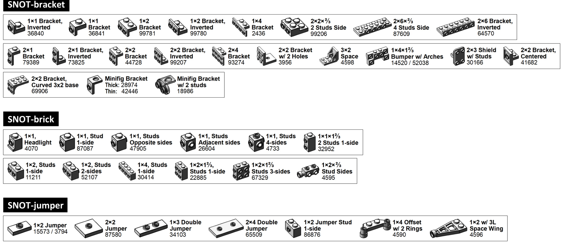
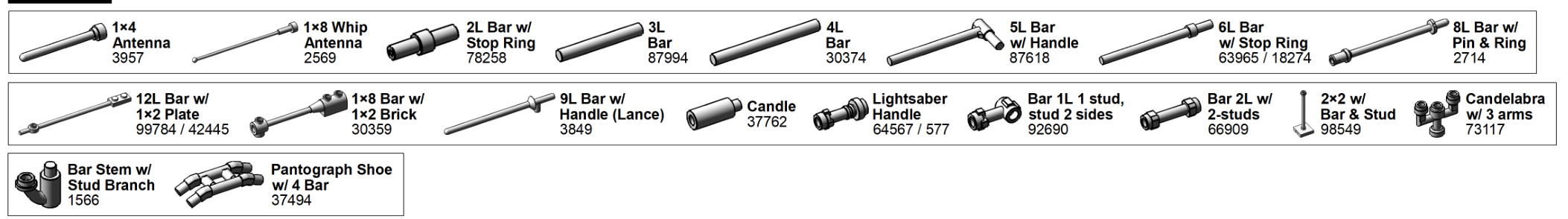
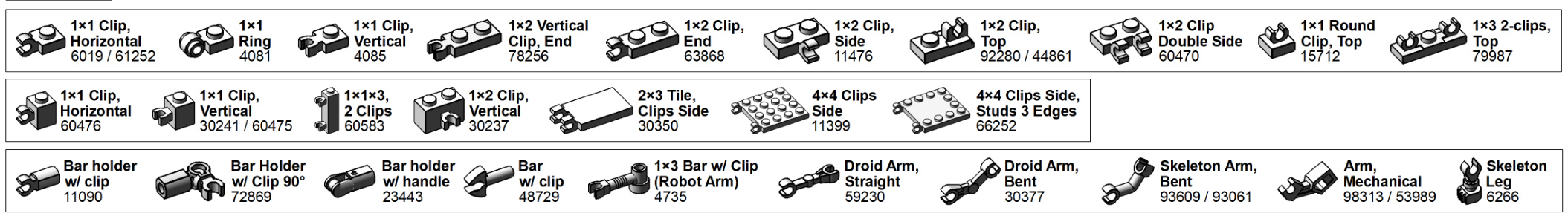
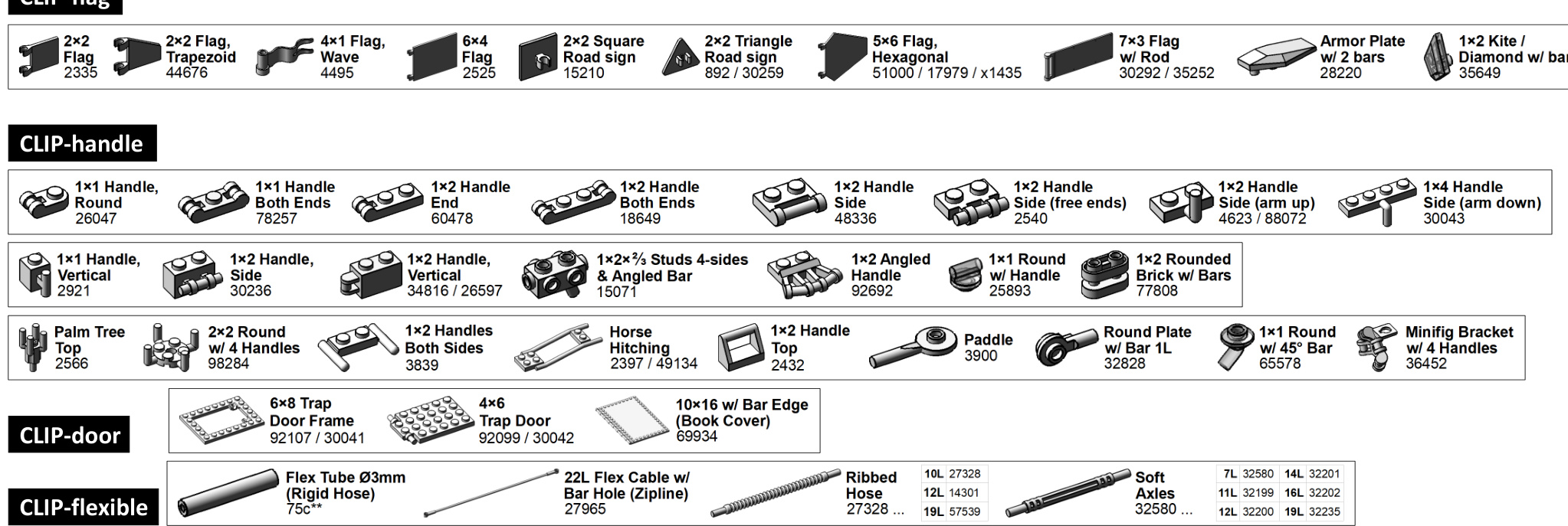
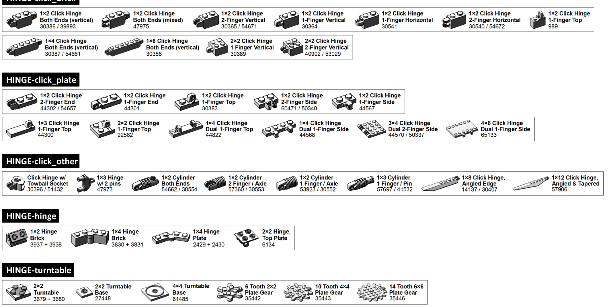
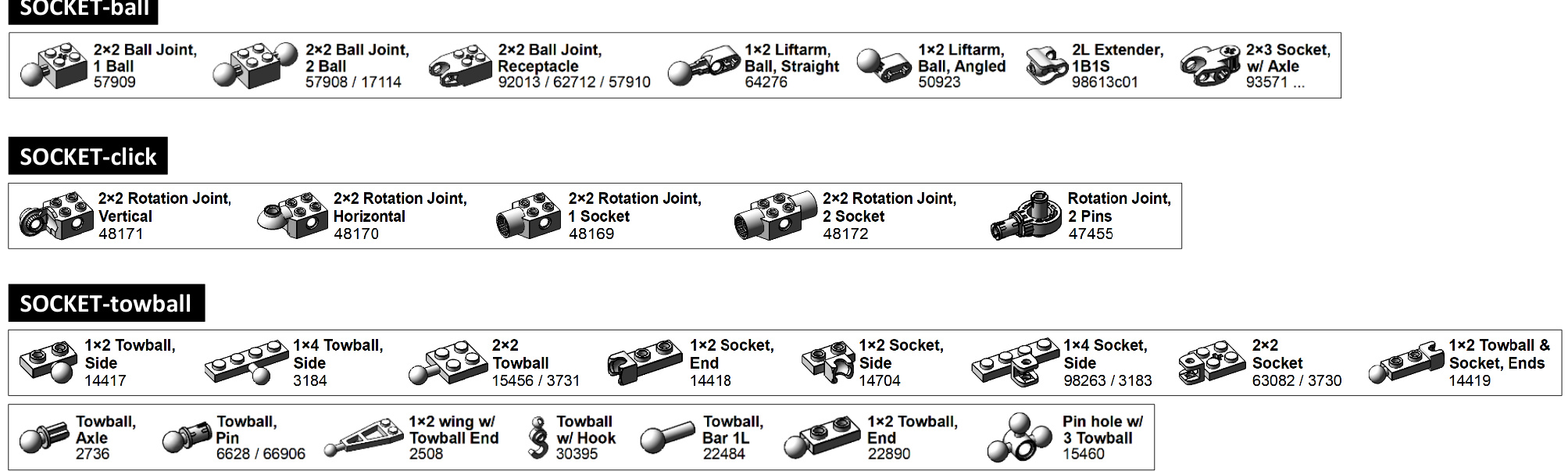
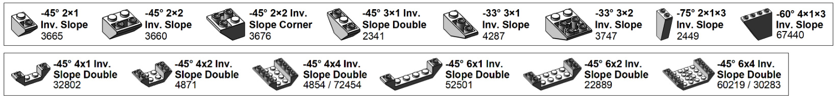
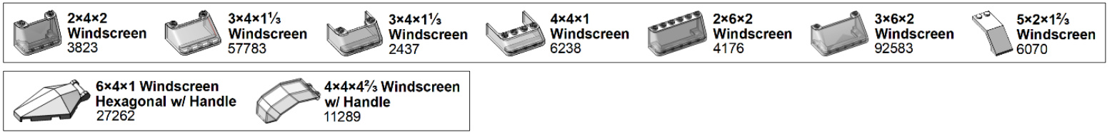
I round out the book with a unique feature that I hope helps builders of all skill levels see the LEGO system at a glance. The Brickopedia (Appendix A) is a graphical reference tool that presents the most common and most reusable elements from available LEGO pieces. Although it does not contain an entry for every single piece ever produced, it does thoroughly examine the LEGO bricks, plates, slopes, and other elements that best define the highly flexible nature of this building system. I have categorized the Brickopedia using some traditional techniques but also using some newly defined criteria and classifications. I set this up intending that you use it as a stand-alone tool; therefore, it does not require a computer or Internet access to be useful.
So sit down with a bunch of LEGO bricks and get ready to build!
T H E L E G O S Y S T E M : E N D L E S S P O S S I B I L I T I E S
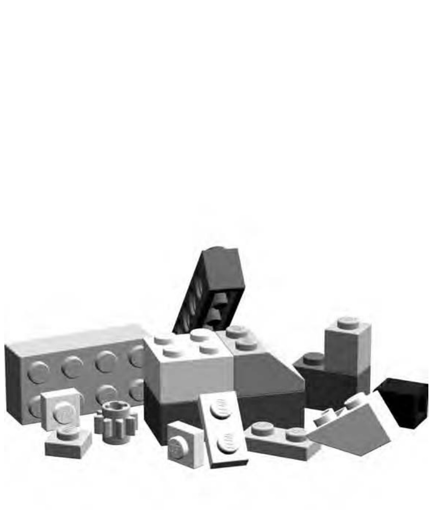
For millions of people around the world LEGO bricks have always had a common meaning: creativity. Regardless of age, we all seem to recognize the sound the bricks make as we rummage through a bucket full of them or a pile on the floor.
Whenever you look at that pile of LEGO pieces, you are looking at something remarkable and yet at the same time remarkably simple. You are looking at the different parts of a system. A system is not only a collection of different bits and pieces but also the ways in which they connect with each other to become a larger object or series of objects. In this chapter, I discuss the LEGO system and what makes it so amazing. I then show you a number of the pieces that make up the system and how they relate to each other. Finally, you’ll take a look at how geometry and color come into play as you’re building with LEGO pieces.
The LEGO system is made up of an enormous number of different pieces, sometimes known as elements. Every piece in that pile is an element. Every element (with only a few exceptions) can connect to any other element in an almost infinite number of ways. A handful of pieces can be combined to form a wall; a few more added on create a roof and then a complete house, then maybe a car and a driveway to park it in. Tomorrow those same elements can be taken apart and recombined to create a deep space cruiser, a sculpture of a calico cat, or even a fortress with a group of medieval knights.
A Brick Vocabulary
Take another look at that pile of LEGO pieces on the floor (or imagine a pile) and you’ll notice that not all of them are perfectly rectangular. Some have sloping sides, some are cylindrical or cone shaped, and some are much thinner than others. You’ve got to have a way to identify different features of bricks or you’ll have a tough time learning how to build with them. This section describes the various key attributes of LEGO bricks and puts them into useful categories.
As you read about the different types of LEGO pieces, you’ll undoubtedly find many that are familiar to you and that already exist within your own collection. At the same time, you are likely to come across others that you haven’t seen before and that you may not yet own. Of course, that’s part of the overall enjoyment of LEGO as a hobby. As you buy new sets or find used pieces at yard sales or thrift shops, you discover new parts that in turn open up new building options.
Sizing Up the Elements
Throughout this book, I often refer to the size and shape of various LEGO pieces, but before I do, I need to provide you with a foundation for these references. Let’s begin with the basic brick, as shown in Figure 1-1.
When I speak of the LEGO system, I consider the (pronounced “one by one”) brick to be the standard upon which I base all other measurements. This, in turn, makes it easy to describe the size and shape of other bricks. For example, if you put two bricks next to each other, you see that they are the exact same size as the next largest standardsized brick. They make a brick, as shown in Figure 1-2.
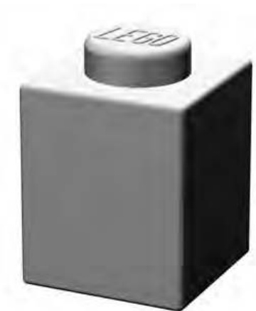
Figure 1-1: brick shown much larger than its actual size
In addition, if a piece is the same height as a , I say it is “one brick high.” A brick that is the same height as a brick but is twice as long is called a brick.
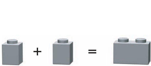
Figure 1-2: Two bricks added together equal a brick
It’s common to put the shorter dimension (the width) ahead of the longer one (the length). Similarly, the element shown in Figure 1-3 is a brick (the equivalent of two ’s wide and four ’s long). I’ll use these measurement standards throughout this book to describe the various LEGO pieces.
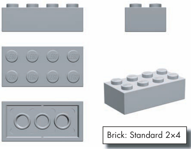
Figure 1-3: Anatomy of a brick. When you see it from all sides, you get a sense of its general size and shape.
Another important standard that you will find in this book is the use of the capital letter as a substitute for a brick’s length. For example, I might talk about a bunch of (pronounced “one by en”) bricks that I used to make the outer wall of a building. In this case, the capital N represents a number of possible brick lengths, such as , , , and so on. Rather than list all of the assorted sizes, it is sometimes easier to replace the last number with an N and allow the description to apply to a range of brick sizes.
The Stud
The stud is a part of almost every LEGO piece, and you use it to measure the length or width of any given piece. The stud (shown circled in Figure 1-4) helps define the look of a LEGO element and it is integral to how the entire system functions.
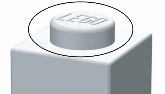
Figure 1-4: The stud gives every element half of what it needs to connect to almost any other element.
The brick shown in Figure 1-4 has exactly one stud. In fact, refers to the fact that our base brick is one stud wide and one stud long. Similarly, the element shown in Figure 1-3 is two studs wide and four studs long.
The Tube
The tube is the other half of the mechanism that helps bricks stick together. Tubes capture the studs so that you can join LEGO elements and know that they won’t fall apart. You can see the tubes by simply looking beneath most LEGO pieces, such as those shown in Figure 1-5.
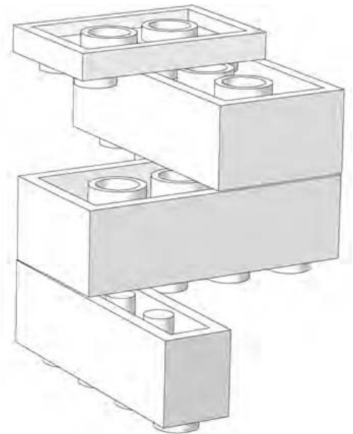
Figure 1-5: The underside of LEGO elements reveals the other half of the secret that locks bricks together.
Figure 1-5 uses a simple upside-down sculpture to demonstrate the way in which the tubes work with the studs. Different types of elements have variations on the tube design. In Figure 1-5, you can see that the thinnest piece (at the top of the illustration) has shortened tubes, whereas the bricks beneath it have longer tubes inside of them. The brick (at the bottom of the sculpture) has thin posts rather than hollow tubes. Despite the contrast in their sizes, they all serve the same purpose: the tubes wedge together against the studs of the piece below to hold the bricks together.
The Brick
Although it is tempting to refer to all LEGO pieces as bricks, it is more accurate to use this term only when talking about certain elements. The label brick is generally given to a type of LEGO part that is the same height as a standard element, like the ones shown in Figure 1-6. A brick should have straight sides and a rectangular shape when you view it from the side.
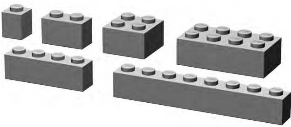
Figure 1-6: An assortment of standard bricks
A LEGO brick is not unlike a real brick that you might find making up the outside walls of a house, an apartment building, or a school. In some respects, the plastic versions are used much as you would use their clay or concrete counterparts. You can use them to create the walls of buildings, but you can also use them to create vehicles, cities, moats, airplanes, and so on.
Using Various Brick Sizes
You will use bricks in a variety of ways: they may find their way into miniland style figures (featured in Chapter 4), mosaics (detailed in Chapter 8), small-scale animals, or just about any model where small detail work is required. In some ways, this is an extremely flexible brick that is sometimes overlooked.
Among other things, and bricks are handy for creating columns for either true structural support or just for ornamental purposes. I’ll explore this technique in-depth in Chapter 2.
In many ways, the longer bricks in the category represent the backbone of the detail-building portion of the LEGO system. They have an enormous number of uses—far too many to fully represent here. One of the first uses that comes to mind is that they may function as the standard walls for virtually any small building. They provide a reasonable to-scale rendition of the thickness that you would find in real world walls.
Now let’s move on to the wider pieces. It’s hard to imagine the LEGO system having found as much long-term success without the association it has come to have with the brick. For many builders who recall time spent rummaging through a pile of pieces, the represents a standard image of a LEGO brick. This piece in particular finds its way into many models; both official sets and original creations by every class of builder.
On their own, these pieces may seem clunky and old-fashioned; they aren’t particularly sleek or smooth and don’t seem to offer much beyond their rectangular shapes. But for many projects, they represent the core material onto which other elements can be added. They are the true bricks of the LEGO system in every respect.
The Plate
At first glance, the common plate (shown in Figure 1-7) may not seem as useful as its big brother, the brick. After all, it takes three plates stacked on top of each other to equal the height of any regular-sized brick. However, that is exactly what makes the plate such an effective building tool. Because it’s only one-third as high as a full-sized brick, you can use a plate to add subtle detailing, internal bracing, or realistic scaling to almost any model.
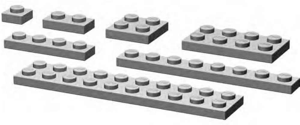
Figure 1-7: An assortment of standard plates
As noted earlier, the underrated plate is often the little piece that could. Plates can be among the most useful of elements and are found in many of the same length and width combinations as bricks— , , , , and so on.
Using Various Plate Sizes
Plates of the variety can find their way into almost any model, from the smallest automobile, to artistic mosaics (see Chapter 8 for more on mosaics), right up to helping flesh out the largest of sculptures (like those in Chapter 7). Similarly, you can find and plates in a range of applications and, thankfully, they are available in an equally large number of colors.
Longer plates have a huge number of uses; you can use them for projects ranging from building helicopter blades for small-sized rescue machines to creating long colorful stripes on the sides of a locomotive. Another area in which they shine is in helping tie together several columns of bricks or other plates that have been stacked vertically to create a visually interesting pattern. (We’ll look more at construction techniques in the next chapter.)
Although the bricks represent the foundation of the brick class, the , , and plates are the working class elements that allow you to accomplish a lot with a minimum amount of material. Throughout this book, I will hit on the idea of using a piece that is only as big as it needs to be. Shorter plates will pop up again and again as we drive toward that goal.
Beneath many a large-scale model are longer plates that hold even larger or plates together. Often plates allow some areas to remain open or exposed, which in turn allows you to add more detail or structure to the model.
The Slope
When you dig through your LEGO pieces, you’ll usually come across what look like ramps for very tiny cars. These are slopes, so named because one or more sides slant from top to bottom (see examples in Figure 1-8). Slopes always create an angled surface between the studs at the top of the element and the point at which that element meets the piece beneath it. Slopes come in a variety of angles from 25 to 75 degrees (with 33- and 45-degree angles being the most common).
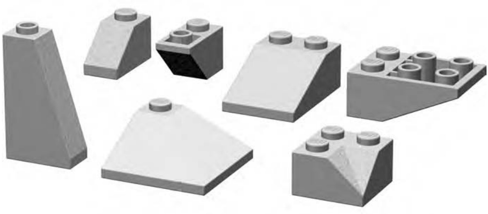
Figure 1-8: Slopes come in a variety of angles and shapes.
Although slopes are sometimes called roof bricks, they can do a lot more than simply cap off LEGO houses. They can add character to almost any model by helping to soften the harsh square edges that otherwise result from using only standard bricks. They can give beveled wings to an airplane, create a reasonable facsimile of an evergreen tree, or be used to put the roof on just about any kind of building.
In addition to their standard form, many slopes are manufactured in an inverted variety where the slant is found on the underside of the brick. An inverted slope is what you might see if you put a regular slope on a mirrored surface (see Figure 1-9). Of course, you can put your LEGO elements on a mirror; just don’t expect them to realize how gorgeous they are.
Specialized Elements
Within the LEGO system, certain elements defy easy classification. A few examples are shown in Figure 1-10. These pieces are either entirely unique or are just different enough from other elements so that they require a category of their own. Many times these pieces are unique because of their shape or perhaps because of the way in which their studs are oriented.
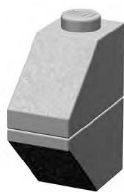
Figure 1-9: These two slopes are nearly mirror images of each other. Many slopes come in both a standard and an inverted variety.
Although standard bricks and plates are inherently useful, the pieces in this category have some type of extra functionality. They are useful in many ordinary but also many specialized situations.
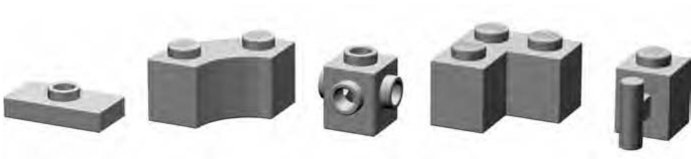
Figure 1-10: Specialized elements can take on a variety of shapes and sizes.
Other classification systems (typically those used on the Internet to catalog, track, or sell elements) tend to sort specialized pieces into existing standardized categories whether the fit is good or not. What happens as a result is that it becomes a challenge to try to find some of these pieces. For example, the well-known offset plate (shown on the left in Figure 1-10) is often described as a plate with a single stud in the center. Other resources label it as a modified plate or a jumper plate. However, it could just as easily be called a tile with a stud in the center, because its surface is more tile-like than it is plate-like. Without a specialized category, it is not the easiest part to classify.
One subcategory of specialized pieces will be wheels. Although it’s certainly possible to use them for other things, they are most often used for one obvious and specialized purpose. See the Brickopedia for a few samples of these elements.
Technic
Originally developed in the 1970s, the Technic portion of the LEGO system was first released in sets known as Technical Sets. They promised to add realism and complexity to regular LEGO bricks, and the models certainly reflected that. The key to adding realism was, in fact, that the new pieces (gears, bricks with holes, axles, and so on, as shown in Figure 1-11) were very much compatible with elements already in existence. In other words, if you wanted to buy or build with the new sets, you didn’t have to start building your LEGO collection again from scratch. You could buy a little blue go-kart with the working steering and the one cylinder motor, and you could use your own blue bricks to add details to it that didn’t come in the factory-made kit.
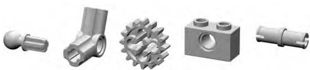
Figure 1-11: Technic parts cover a large range of strange shapes and serve to enable more realistic and functional models made from LEGO elements.
In theory, you could build almost an entire model using nothing but Technic elements, but by adding in some of your regular system parts, you can enhance that model and produce a more finished result.
To classify Technic pieces, you need to add additional subcategories to what is, in essence, already a subcategory. In order to keep things as simple as possible, the number of divisions has been kept to a minimum, and the descriptors have been similarly kept lean. Since Technic gets its own chapter later on (Chapter 9), I’ll leave any examination of this category for that part of the book.
Arch Pieces
At first glance, you might think that arch pieces (like the ones in Figure 1-12) are too specialized to be of much use for more than architectural detailing. And although they serve their primary purpose without compromise, they can also add character and shape to models of all types, not just buildings.
Arch bricks are useful for creating arches, especially on the exterior of buildings, but they can appear over many things. For instance, you can have an arch over a doorway or above windows. You will also find arches repeated to create visually exciting geometric patterns along the top edges of buildings, or you may find them used on otherwise plain walls to create sections sometimes filled with other colors or patterns.
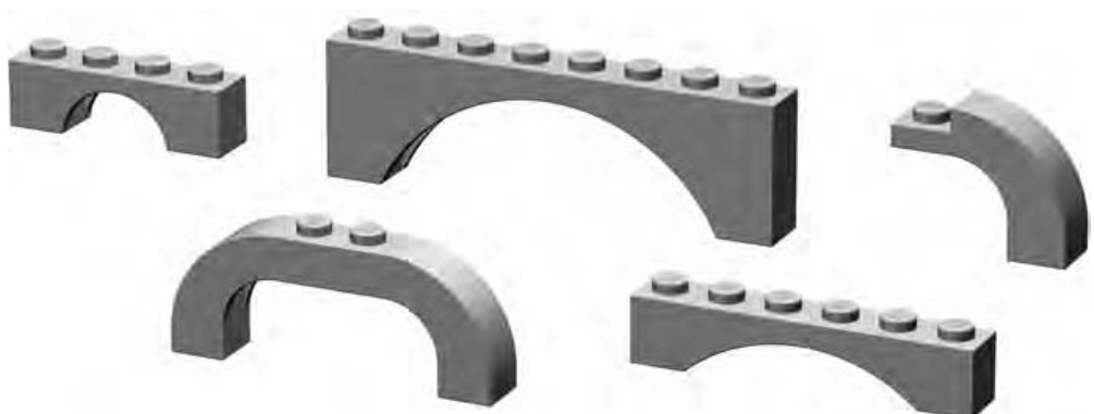
Figure 1-12: Among the most graceful of LEGO elements are the arches. They come in several sizes and styles.
Using an arch as an arch is a no-brainer. Using arches of varying sizes and shapes is a little more difficult. In many cases, it’s best to draw your inspiration directly from the building you are attempting to copy, or at least a similar type of structure if you’re building a piece of architecture that has never before existed. Picking out how arches are used on buildings is not unlike working one of those brainteaser puzzles where you have to figure out how many triangles are really drawn among the dozens of intersecting lines on the page.
Tiles and Panels
Standard tiles are easy to spot (see Figure 1-13); they’re like a plate without studs. Cylindrical tiles are similarly easy to figure out because they look like tiny smooth manhole covers.

Figure 1-13: Tiles have a tiny groove at their base that allows you to remove them more easily.
Panels, on the other hand, come in a wider variety of shapes and sizes (see Figure 1-14). In some sense, panels are like tiles with other tiles attached at right angles to form a thin vertical wall or two. Panels may or may not have studs.
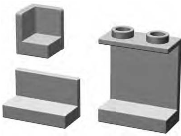
Figure 1-14: Panels come in a variety of shapes and sizes.
Cylinders and Cones
Cylinder elements have a cylindrical shape, like a coffee can or a drum (see Figure 1-15). Cones, on the other hand, are sort of like upside-down ice cream cones. Although only a few elements fall into the standard cylinder or cone categories, what they lack in number they make up for in uniqueness.
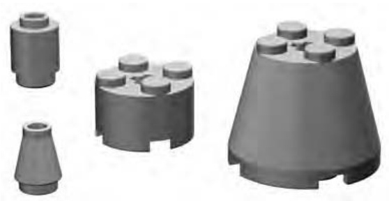
Figure 1-15: Cylinders come in standard vertical-walled varieties and also sloped versions known as cones.
From tree trunks, to light posts, to the nozzles on the ends of water cannons, you’ll find a varied set of uses for cylinders and cones.
Cylinder Plates
Cylinder plates, as their name suggests are just shorter versions of their full brick-height cousins. The tiny cylinder plate (sometimes known as a pip) and the useful plate (both shown in Figure 1-16) are the only two elements that make up this subcategory, making it among the smallest you’ll see.
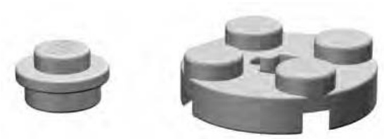
Figure 1-16: A pip sits next to its big brother the cylinder plate.
Baseplates
It’s not hard to confuse large standard bricks with small baseplates. So where do large bricks end and baseplates begin? For purposes of this text, assume a baseplate is an element with a waffled underside to which no other bricks can be attached. These baseplates are, in fact, thinner than even a standard plate, as shown in Figure 1-17. They may be plain (having only regular studs on top) or may have designs (such as roadways) printed on them.
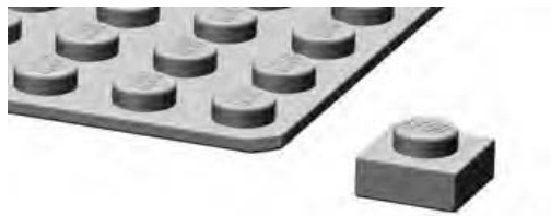
Figure 1-17: A plate is used to show the difference in thickness between it and a waffled baseplate.
Baseplates give you a foundation upon which to build a model, whether it’s a building, a machine, a sculpture, or just about anything that requires a platform to steady it or allow it to be transported or displayed.
Decorative Elements
Standard bricks, plates, and slopes are obviously useful for creating a basic model. Sometimes though, you need to add a bit of character to your creations. Decorative elements can perform that task for you by allowing you to add windows, doors, trees, and so on. As you can see in Figure 1-18, they take many forms.
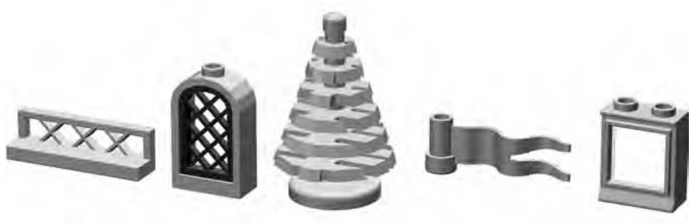
Figure 1-18: Fences, windows, trees, and flags are just a few examples of decorative elements.
Precision, Geometry, and Color
Now that you have a handle on basic LEGO-related terminology and some sense of how parts can be categorized, let’s look at a few other areas of the LEGO system.
Why Precision Manufacturing Matters
It doesn’t take very long to realize something very important about LEGO pieces. Every element is manufactured to a very high degree of precision, not unlike the accuracy seen in the manufacture of aircraft parts. Because this precision applies to such a small scale, this tight control of plastic molding may not be evident immediately. If you snap a few bricks together and they are off by a hair’s width, it probably won’t bother you too much. But what if you begin to stack up more and more bricks? How long will it take before even a small difference in quality control begins to show itself?
Take Figure 1-19 as an example. Imagine you are making a doorway. On the right, you use properly made bricks, each exactly the height it is supposed to be. On the left side, you use a handful of bricks that weren’t made with the same precision and care. Perhaps they were made just a tiny bit too short, say, by about the thickness of a pencil mark. It’s clear from Figure 1-19 that only a few layers of bricks with such a manufacturing variance would begin to play havoc with your construction. How would you join these two mismatched walls?
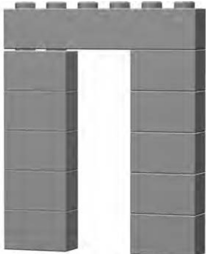
Figure 1-19: Imagine the difference a tiny error makes when multiplied by a number of bricks.
Height, of course, is but one of three essential dimensions that must match in each and every element. Differences in length or width would also quickly become apparent because you would find that a brick wouldn’t press down normally onto the pieces beneath it. Studs would be out of alignment and finishing even a modest-sized model would become nearly impossible.
The same attention to detail must also be given to things like the height and width of the studs themselves, the height and thickness of inner tubes, the diameter of the walls of bricks and plates, and so on.
Fun with LEGO Geometry
When you look at the base measurement piece (the brick) you’ll find that it is a vertically oriented rectangle with a ratio of 5:6 (width:height). Figure 1-20 shows these measurements applied to a brick.
This means that five bricks stacked on top of each other are exactly the same length as a standard brick, as shown in Figure 1-21.
This happens because the five bricks are each six units high. So five times six equals thirty. Similarly, each stud of the represents five units of width. So six studs times five equals thirty again. Note that we take into account only the dimensions of the brick walls and disregard the height of the last exposed stud. We’ll see this interesting geometry come into use in Chapter 8 when we look at mosaics.
Other interesting geometries are available within the system. For example, the tubes under a standard brick or plate are the same distance apart as regular studs, and the inner diameter of the tube is the same diameter as the stud itself. This allows you to place a brick or plate on top of exposed studs where the number of studs is equal to or less than the number of tubes available, as shown in Figure 1-22.
This represents one of the few times, other than when you are using offset plates, that you can offset elements from one another by a value of one-half stud rather than a full stud.
Consider, too, the relationship between the height of a standard plate and a standard brick, as shown in Figure 1-23.
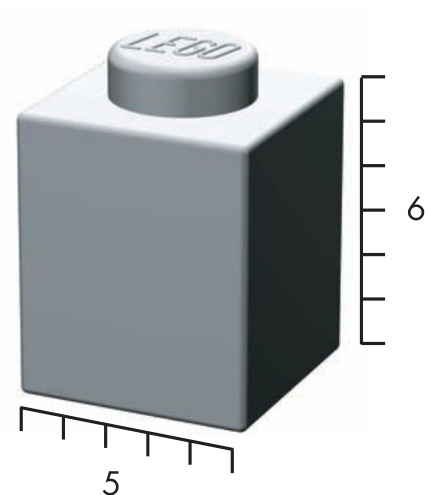
Figure 1-20: The 5:6 ratio of width to height applies to all standard LEGO bricks.
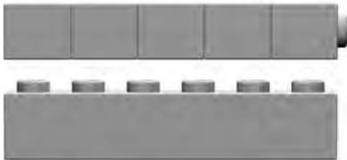
Figure 1-21: The 5:6 ratio of brick height to brick length
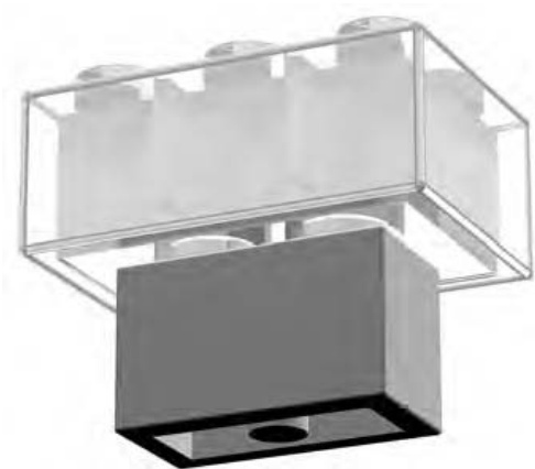
Figure 1-22: Studs inserted into tubes, not alongside them
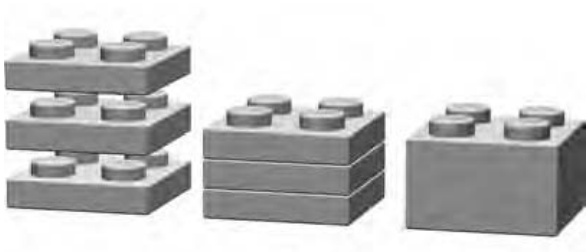
Figure 1-23: Three plates stacked together will always equal the height of one standard brick.
It’s quickly apparent that three plates equal a brick, but that is not where things end. This simple and elegant fact represents a wealth of potential building patterns and techniques. One fairly easy application of this fact is that you can use plates to create visual illusions within the context of walls or other structures. For instance, the white stripe seen in the fire truck Figure 1-24 shows how you can stagger plates through several layers of other plates and bricks to create the effect of an angle.
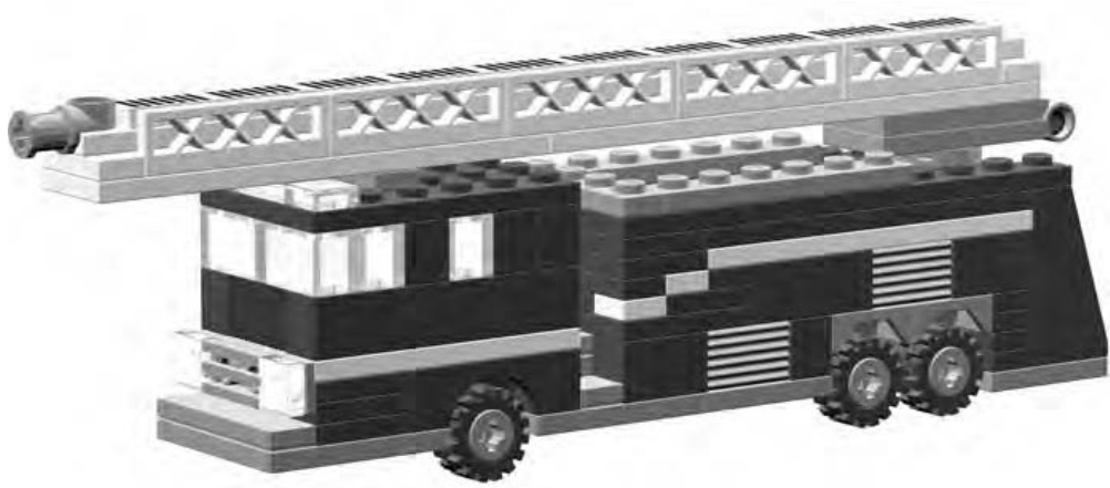
Figure 1-24: Fire truck with stripes made from plates
I’ll show you other techniques for using plates throughout the book. As you move on to some of these best practices, you can rest assured that even your wildest designs and ideas can be fulfilled thanks to a system of bits and pieces that have been carefully created to interact with each other as easily as they interact with you.
The Colors
For many years, LEGO bricks were epitomized by the primary colors in which they were available: red, yellow, and blue. In fact, in 1958, when the original patent was issued for the knob and tube design (which defined the modern LEGO brick), only seven different colors were being made: white, black, red, blue, yellow, green, and clear. Of course, today’s sets are being released with colors that include mossy green, maroon, pale blue, dark grey, bright orange, and even pink!
Given LEGO’s original color limitations, builders had to improvise to create new colors from the limited existing ones. The trick they developed to create new colors was to place one or more colors next to each other to create a sense of blending. For example, a white brick may take on a subtle grey tone when placed next to a black element. Similarly, a yellow piece will shift slightly toward the orange part of the color spectrum when placed next to a red brick.
The colors you chose to use in your models can add realism, character, or even a sense of humor that might not otherwise be telegraphed by the bricks themselves. For instance, a fire engine you model in red or bright yellow will probably look more like the real thing than if you built it from blue or grey bricks. A snowman sculpture will look more like what people expect if he is constructed in a traditional white scheme. (Although you might decide to put red horns growing out of his head to create something playful or mischievous.) A fairground ride might look more exciting and fun if it uses a variety of colors in playful patterns of reds, blues, and yellows. Color plays an important part in almost everything you build.
For the Color Challenged
One problem that often besets new or younger builders is a lack of enough bricks in any one color that they can use to give a model a consistent look. This can be frustrating, but it doesn’t have to stop your plans for building sophisticated models. There are two ways you can make the most of the bricks you have, in whatever colors they may be, without spending a fortune topping off your stocks.
- Match the models you build to the bricks you have. Build small models that let you stay within a single color or perhaps two.
- Use multiple colors in planned ways to maximize your entire collection of elements. Many vehicles, buildings, animals, and other subjects are either naturally multicolored or allow for adaptation so they can be modeled in other colors.
Even official LEGO sets have used limited color schemes to great effect. Some sets contain only a smattering of colors. Sets like these offer two huge benefits: they provide you with ideas for using limited colors effectively, and they add healthy quantities of two or three colors to your collection.
For example, imagine that you have one or more official sets that contain a lot of red and white elements. Aside from the model(s) suggested in the instructions, you might also find that you have enough parts to build a simple sculpture like a candy cane in time for the holidays (as shown in Figure 1-25).
Or you could use a similar color scheme to put together a small lighthouse like the one shown in Figure 1-26. The point is that your limited palette of colors doesn’t need to limit your imagination.
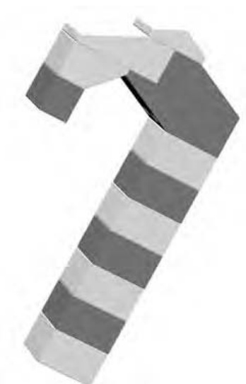
Figure 1-25: Having limited colors means using what you have to the best of your ability.
One thing to consider is that you can buy more than one of the same set. Although this may seem silly at first, it makes perfect sense if you are trying to build up your collection of a certain color or colors. This is especially true if you can find the set on sale or perhaps you can ask to receive another copy as a gift.
NOTE
For instructions and color images of the lighthouse, visit www.apotome.com/ instructions.html.
Review: The LEGO System
You may have noticed that you didn’t learn much about actually building with LEGO pieces in this chapter. That’s okay; there’s lots of that to come. You did learn about the basic framework and terminology of the LEGO system. You’ll use that knowledge to work through the construction techniques and ideas that follow. Being able to tell a brick from a plate makes all the difference as you move on to those more complicated topics. In turn, those practices allow you to create a minifig-scale train station, a three-dimensional sphere you can hold in your hand, and even a mini space shuttle that you get to design from the ground up. Between here and there, I’ll try to explain more of this amazing system, describe its many uses, and hopefully, reveal a few secrets along the way.
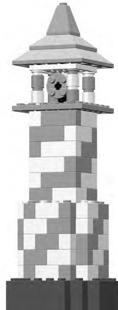
Figure 1-26: The stripe on the lighthouse is achieved by carefully placing just two different colors of bricks. Try building this model using red and white elements with brown or dark gray for the base.
2 B A C K T O B A S I C S : T I P S A N D T E C H N I Q U E S
No matter how old you are, when you sit down in front of a pile of LEGO bricks, one thing never changes: you want to snap a few bricks together. Why this happens is not a mystery. LEGO bricks, like grains of sand on a beach, are meant to be together.
But what are the best ways to join bricks? That depends, of course, on what you’re building. Official LEGO literature goes to great lengths to point out the many possible ways to connect your bricks. For example, they suggest that if you take six bricks, you can arrange them in 102,981,500 different patterns. (Someone at LEGO has a very good understanding of geometry and mathematics or just way too much time on their hands.) Figure 2-1 demonstrates just three of the millions of possible combinations. I’d need an enormous number of pages to show pictures of every pattern.
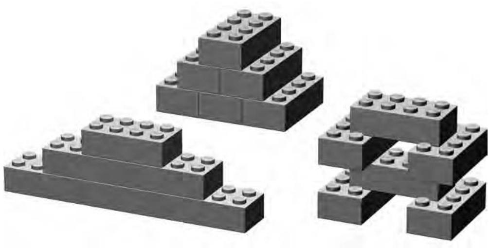
Figure 2-1: You can combine six bricks in many ways.
Decisions, Decisions: The Best Ways to Connect Bricks
Perhaps more important than the number of ways in which you can fasten bricks together are the principles behind how they should be put together.
For example, consider any two bricks. You can connect them in three basic ways, as illustrated in Figures 2-2 through 2-4. You can stack them, overlap them, or stagger them.
Is it best to put them together like this? Like this?
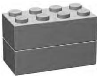
Figure 2-2: Stacked
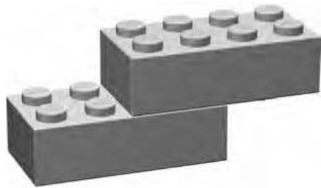
Figure 2-3: Overlapped
Or like this?
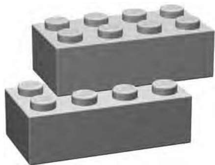
Figure 2-4: Staggered
Each of the diagrams in Figures 2-2 through 2-4 represents a different type of bonding, or joining of LEGO bricks. Bonding patterns are the ways in which bricks are arranged or connected. Let’s look at each of these patterns individually to get a sense of how they can be most useful.
Stacking
Although not the most common way to build, and usually not the sturdiest, at times, stacking bricks one on top of the other is necessary. For instance, a small shop in your LEGO town might have vertical stripes of color that you wish to appear painted on the sides of the building. Or perhaps an airplane needs to have a colorful pattern of lines on its tail section.
Typically your decision to use vertically stacked bricks is driven by aesthetic rather than structural needs. The reason for this is simple: as you can see in Figure 2-5, stacks of bricks, unsupported by surrounding pieces or layers, are generally not very strong.
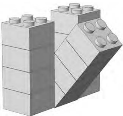
Figure 2-5: Crash! With nothing to support it, the center column of bricks is prone to falling over when you least expect it.
When you do need to stack bricks, make sure that you secure the stacks— both above and below—with longer bricks or plates. For example, as you can see in Figure 2-6, stacked bricks create the vertical stripes on the tail section of a plane. The vertical part of the tail sits on several offset plates, but below that, the stripes are held together by a plate. Near the top, the stacked bricks are locked together by the plate you can see just above the highest slope piece.
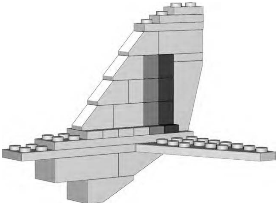
Figure 2-6: When it is necessary to stack bricks, make sure you lock them in place to avoid the Humpty Dumpty effect.
Overlapping
No building technique adds as much to your models as overlapping does. As with real brick walls, LEGO bricks work best together when they sit on top of each other in overlapping patterns. These overlapping connections strengthen the structure and prevent it from collapsing. (Depending on the size of brick you are using, this overlap may be one-half of the brick below, or as little as a small part of the lower brick.) Figure 2-7 illustrates just a handful of different overlap patterns. The ones you use depend on the bricks you have available and the model you are building.
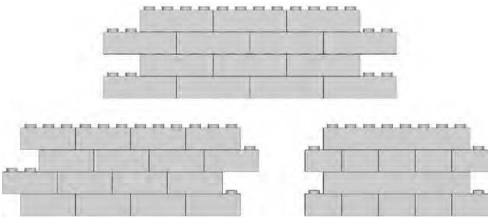
Figure 2-7: Bricks can overlap each other in a variety of patterns.
Overlapping bricks gives your models strength and allows you to fully exploit one of the primary features of the LEGO system: the interlocking feature of elements. Models containing standard bricks and plates almost always utilize one or more overlap patterns. Later in this chapter, I’ll show you how to build walls and connect them together. Those tasks both make significant use of the overlap pattern.
Don’t forget that other elements need to be overlapped as well. Pieces like doors and windows should be secured using this technique to make sure they are solidly built into a wall. In Figure 2-8, you can see this principle in action.
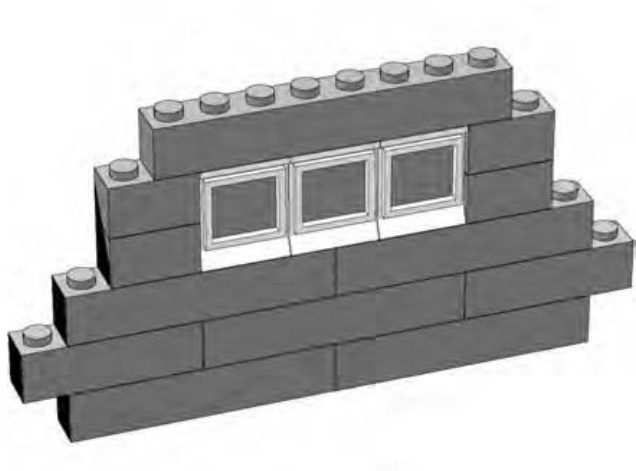
Figure 2-8: A well-placed brick can make the difference between a solid wall and one that will eventually fall apart.
It’s clear in Figure 2-8 just how important overlapping is. You can see that the brick at the top of the wall overlaps not only the windows, but also the bricks to either side of them. This helps create a solid structure.
The simplest way to achieve good overlapping is to simply remember that you want to avoid too many bricks stacked on top of each other, which creates vertical seams. You can see what I mean in Figure 2-9.
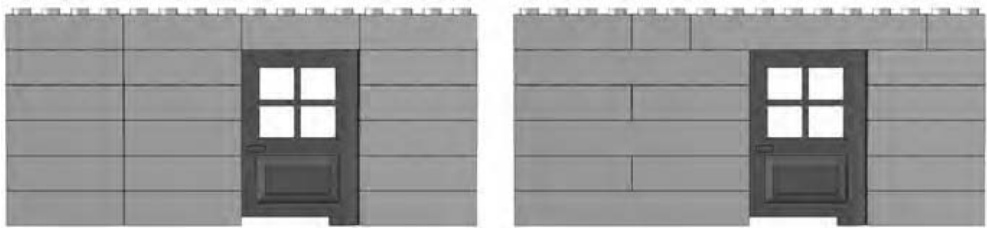
Figure 2-9: A poorly designed wall (on the left) is shown with a properly designed wall (on the right).
The wall on the left in Figure 2-9 was created using the stacking technique you saw earlier in the chapter. You can see how unstable the door would be if you tried to open it because the brick on top of it isn’t attached to anything else. On the right, you can see the better way to create a wall with a door. Notice that the brick over the door is also attached to bricks on either side, just as the windows are in Figure 2-8. This helps anchor the door to the wall and makes sure that they won’t come apart when you least expect it.
Staggering
When you stagger bricks, you set one layer of bricks back from the front edge of an adjoining layer of bricks to produce a stair-step pattern.
Staggering is a particularly important technique when you’re building sculptures (covered in Chapter 7). It allows bricks that are typically square or rectangular to achieve more organic shapes when used in the right combinations. That isn’t its only use of course. Figure 2-10 shows a very common way to use the staggering technique.
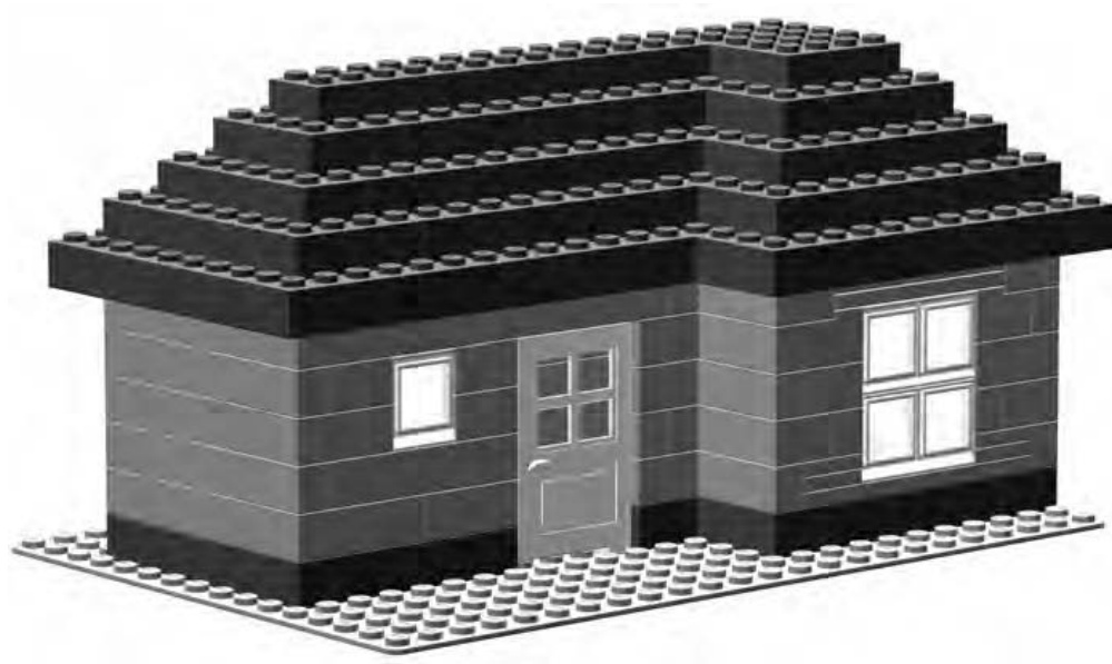
Figure 2-10: You can apply this simple staggered roof technique to a multitude of models.
In Figure 2-10, you see a small house or perhaps a vacation cottage. By staggering the bricks, you can create a roof out of nothing more than standard bricks. In other words, instead of using sloped bricks for the roof, you create one from ordinary elements; this is a popular technique in the LEGO building world. Figure 2-11 shows a portion of the roof in close-up so that you can see exactly why the staggering technique is so useful in situations like this.
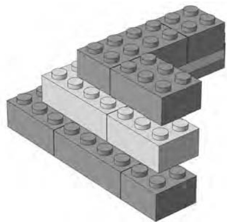
Figure 2-11: Don’t forget to overlap bricks as you stagger the layers.
In Figure 2-11, I alternated the colors of the layers in the close-up of the roof so it’s easier for you to see how I accomplished the staggering. Obviously -sized bricks work best for this technique. Notice that even though I stagger the bricks (to accomplish the slope of the roof), I still overlap them from layer to layer. This combination of two techniques results in a sturdier model.
Building Walls
Walls are one of the most common things built from LEGO bricks. They may be walls for a fire station, a hospital, or a police department. They could also be the walls of a medieval castle or maybe even an alien base on some far-off planet. In the “Overlapping” section earlier in this chapter, you saw how to build a strong wall by itself. Now let’s move on to learn how to connect two or more walls together.
Connecting Walls
In several of the earlier illustrations (Figures 2-7, 2-8, and 2-9), you saw simple walls built with the overlap technique. However, a lone wall isn’t much good if you intend to create a realistic-looking building. The inhabitants of your LEGO world will certainly enjoy their buildings more if you provide them with rooms, doorways, and other basic structures—especially ones that won’t fall down.
But don’t expect to connect two preexisting walls to each other to make a strong pair. It is much better to build them at the same time and have them draw on each other’s strength. Walls should be joined to each other from the very first course of bricks. Figure 2-12 shows the first layer of two walls that will be connected.
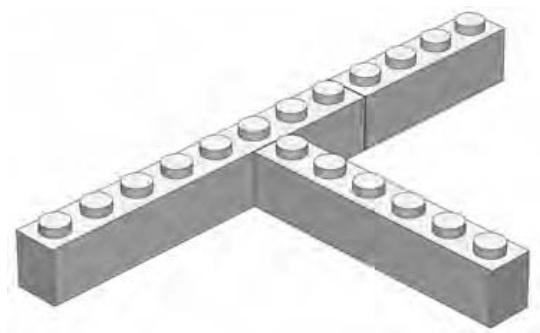
Figure 2-12: The first course of bricks when building a wall connected to another wall
The next course of bricks begins to lock the first layer in place by overlapping, as shown in Figure 2-13. The dark brick ties one wall to another, locking the to the .
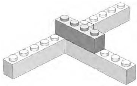
Figure 2-13: The highlighted brick is the cornerstone of the overlap. It connects the two walls beginning with the second course.
This technique is the key to building solid models. As Figure 2-14 shows, as you add the remainder of the second course, the other bricks (in this particular example) aren’t quite as important as the one highlighted in Figure 2-13. They are part of the walls, but not part of what is holding the two walls together.
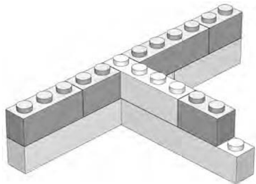
Figure 2-14: The remainder of the second layer is added.
Finally, in Figure 2-15, you can see that the overlapping technique continues to be used to connect the two walls to each other but is also used within each individual wall. This ensures the structure is sound.
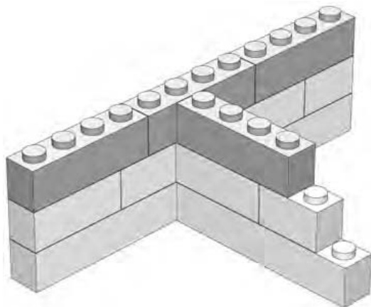
Figure 2-15: Completed example
After just a few layers, you should find that your two walls are firmly supporting each other. Try pushing on either wall, and you will soon see that they can’t be easily shifted. The overlap pattern has given you strong walls, and by connecting them together, you have made them even more stable.
Straight Bricks Can Make Round Walls
Of course, you don’t always want perfectly straight and perfectly interlocked walls. Sometimes you want to create a model that’s a little more organic, or at the very least, less than square.
How can you use straight bricks to form a curved wall? One fun technique is to dig up as many bricks as you can find and link them together, as shown in Figure 2-16.
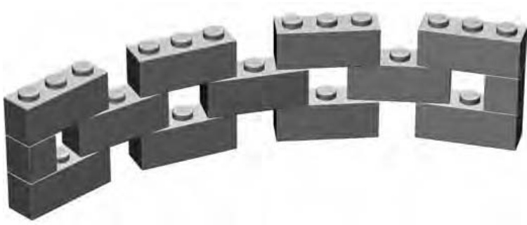
Figure 2-16: bricks joined in this fashion make it possible to create curved or even completely circular walls.
This method allows you to curve a wall as much as you want, even to the point of creating a complete circle. You may find yourself using this idea to make a pen for barnyard animals, the body of a rocket, a fence around a house, and so on.
To create a different look, try adding cylinder bricks to the openings between the bricks. As you can see in Figure 2-17, this makes the wall appear more solid. You won’t be able to curve it as much as the example in Figure 2-16, but it’s still a great technique that will add new shapes to your models.
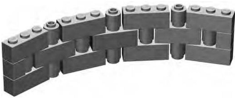
Figure 2-17: A few small pieces can make a big difference in how your wall looks.
By playing around with the length of your wall and the curve of the bricks, you may find that you can even link the ends of the wall into existing square structures (see Figure 2-18). For example, you may be able to take two castle walls and create a rounded corner that connects them. Or, you can try to make a guard tower from the technique and set it on a castle made from regular walls that meet at 90 degrees. By placing round plates at various points under the ’s, you should be able to find combinations that allow you to connect your round wall to the other parts of your model.
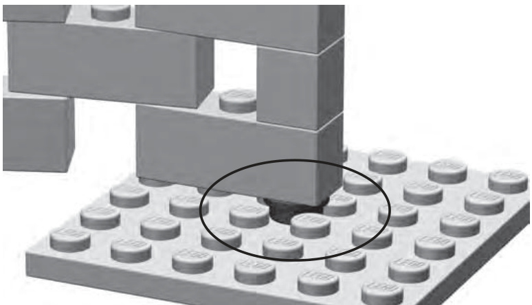
Figure 2-18: Round and square worlds meet. The cylinder plate (circled) is used to anchor the curved wall to a flat surface.
Bracing: Unseen but Not Forgotten
Bracing is the art of reinforcing your models, typically on the inside, to make them stronger and more stable. It can be as simple as adding a few long bricks to strengthen otherwise unsteady structures, or as involved as building columns and beams within a larger model to allow it to be handled, transported somewhere, or even just stand up without falling down.
Bracing Beams Columns
In Figure 2-19, you see some simple walls. They could be the outsides of an office building, the sides of a grandfather clock, or maybe the beginnings of a tall but slender air traffic control tower. You also see some other bricks (marked A and B) that seem to connect the other walls. This reinforcement, made up of a central column and two horizontal beams, is bracing that is used to make the model stronger.
The amount of bracing required varies from model to model—from none for smaller models to lots for large buildings and towers. Bracing your model properly can give it a very solid structure that is particularly useful for transporting it (to a public display or to a friend’s house) or even just playing with it.
Why not just fill in the area inside the building completely and make it solid? Although this might work for some smaller models, it makes larger ones heavier than they need to be, and it most definitely uses more bricks than you probably need. Why hide your bricks needlessly? Use what you need for support and no more. You can use the bricks you save by building efficiently to build other parts or other models.
Bracing is really functional construction and does not necessarily have to look pretty. The great thing about this technique is that you can use just about any bricks at your disposal to beef up a model from behind or underneath. After all, no one is going to see the bricks, so it doesn’t matter what color they are or whether they are even the same color.
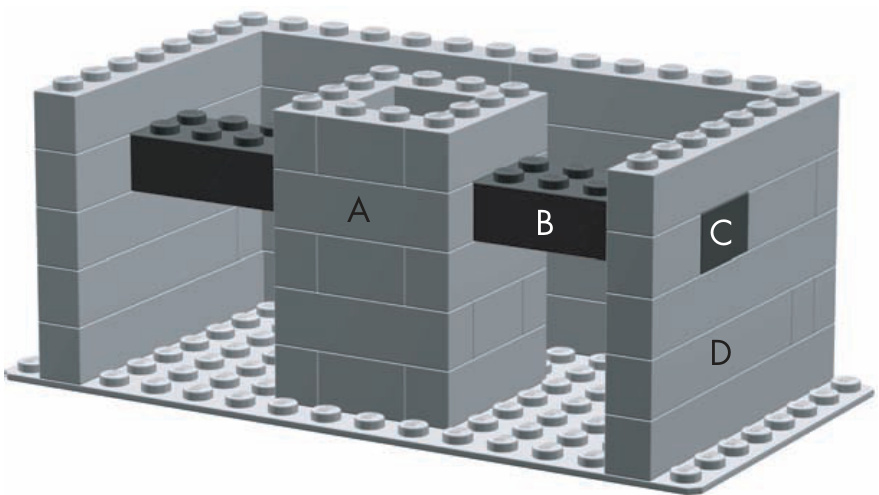
Figure 2-19: A peek behind the scenes shows how columns and beams come together to form bracing for this representative building.
In Figure 2-19, the column (labeled A) stands away from the walls of the building. The beam on the right (labeled B) extends from the column to the outside wall (labeled D). The dark square (labeled C) in the wall is really the end of beam B. It is built into the wall and creates a strong link between column A and wall D.
To better understand bracing, you need to learn a bit more about columns and beams.
Beams
You saw one form of columns in Figure 2-5. Normally, though, you wouldn’t expect to see columns lined up next to each other as in that example. Rather, you would find them as the corners of buildings, the structures on either sides of doorways, or as supports for wide floors or ceilings.
One reason that the columns in Figure 2-5 were able to tumble was that there was nothing holding them together. That’s where beams come into play. Beams are the horizontal equivalents of columns, and they work handin-hand with them to form strong structures.
A beam can be as simple as a single brick (such as the one shown in Figure 2-20) you use to connect two parts of a structure that would not otherwise touch each other. Or, a beam can be a much larger and much more complicated substructure. A substructure is a portion of a model that you build separately and then join to the main model. An example could be something used for support, like the composite beam shown in Figure 2-21, or it could be something more visible, like the ladder on a fire truck.
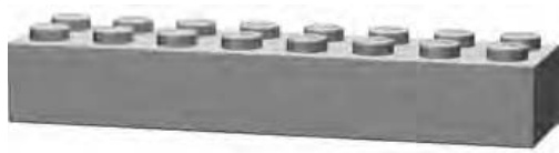
Figure 2-20: A beam can be as simple as a single brick.
You can make composite beams (see Figure 2-21) from a mixture of bricks and plates or just several layers of bricks. You can build them very long, yet they still remain strong.
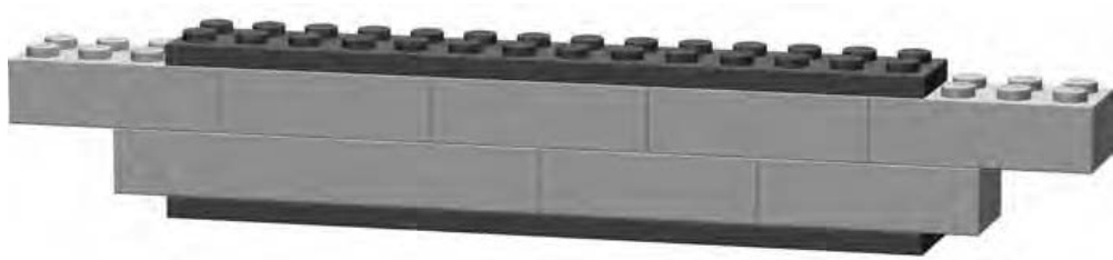
Figure 2-21: A composite beam, made from bricks and plates
Notice (in Figure 2-21) that overlapping plates (with each other or with full-height bricks) is just as critical as it is when you are building with bricks alone.
Given how important they are, building strong beams is obviously a big concern. Let me first show you how not to do it.
How Not to Build a Beam
Set up a few bricks to resemble Figure 2-22.
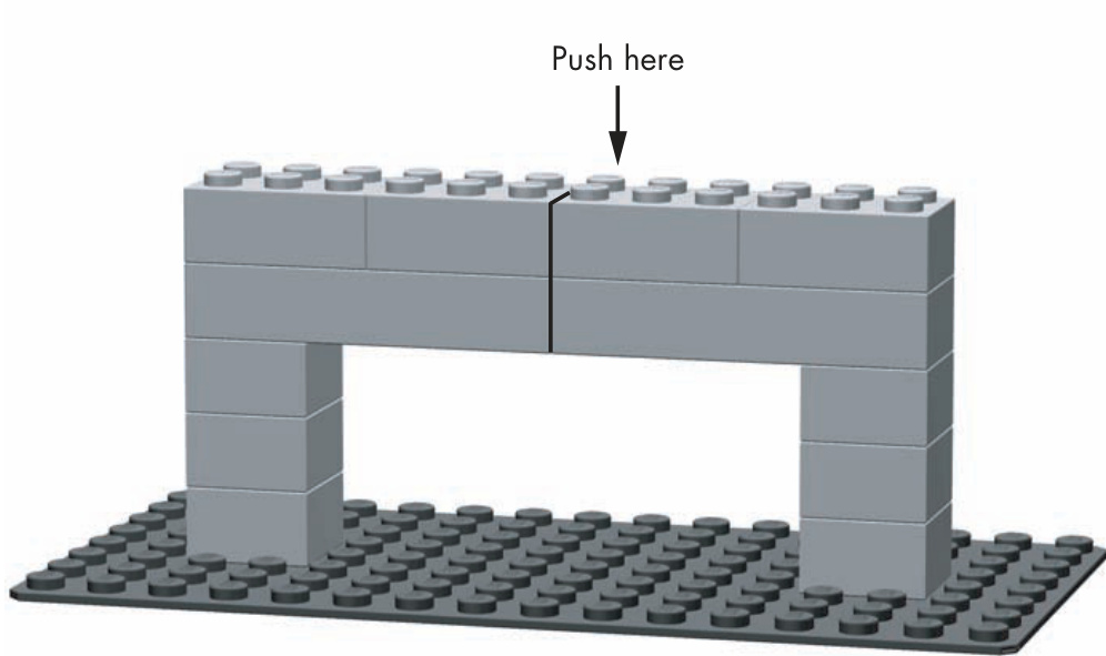
Figure 2-22: When you set up your example, pay close attention to the bond patterns I used.
To conduct this experiment, simply push down with your finger on the brick shown in Figure 2-22. You’ll find that with very little effort, the bricks you set up between the two columns quickly break apart and fall down. You have just seen a structure fail, which is typically something that you’d rather avoid in most of your models.
The Right Way to Build a Beam
Now try setting up a similar set of bricks but in a slightly different pattern, as shown in Figure 2-23. Carefully note the positions of the bricks and where they overlap. Now when you push down from above, you should find it nearly impossible to cause the beam to fail. It should become quickly apparent why it is so important to overlap bricks.
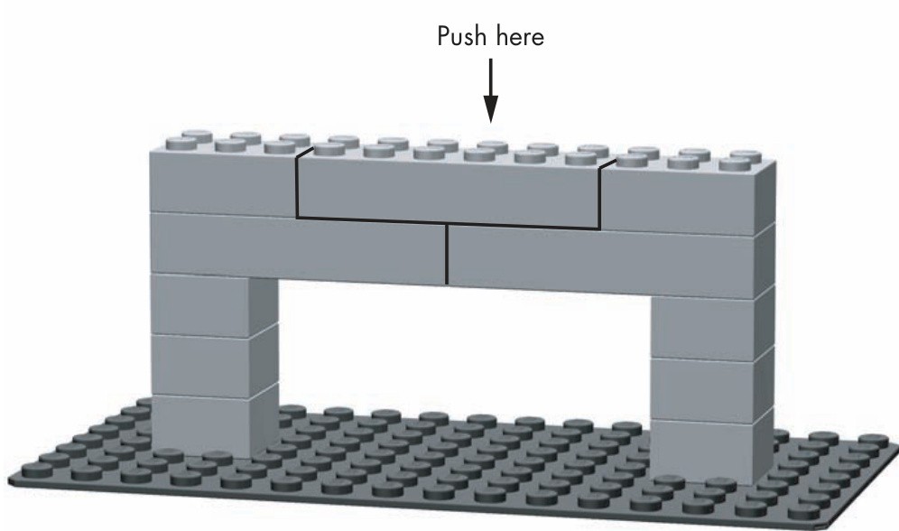
Figure 2-23: This example uses a simple overlap pattern to ensure the beam won’t buckle under pressure.
You could use the beam in Figure 2-23 to connect the outer walls of a large building or you might even find it over top of the large opening on the front of a LEGO aircraft hangar.
Columns
Columns are the other half of what you use to brace larger or unstable models. Typically you’ll use one or more columns to support beams that connect to the sides of your model. Columns can take many different forms, as seen in Figures 2-24 through 2-27.
The Simple Post
In Figure 2-24 you see nothing more than bricks stacked on top of each other. A simple column like this one might suit some of your projects quite well. It’s important that you never make anything more complicated than it needs to be. Just be sure the post doesn’t get too high, because this type of column lacks the strength of the other examples.
In addition to the bricks in Figure 2-24, it is also possible to make a simple post from ’s, , or just about any other sized brick.
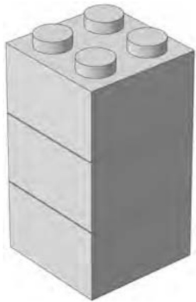
Figure 2-24: The simple post
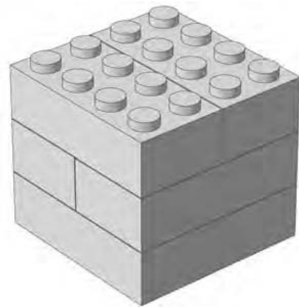
Figure 2-25: The compound post
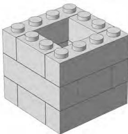
Figure 2-26: The chimney pattern
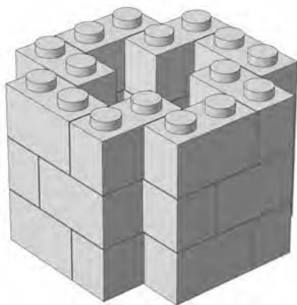
Figure 2-27: The keyhole pattern
The Compound Post
Figure 2-25 is a much more sturdy column, though one that obviously consumes more bricks. Unlike the version, this column can withstand a certain amount of pressure from any side without crumbling. It’s also about as simple to build as anything you could ask for. This is an excellent choice when you are creating a number of columns quickly (perhaps even to use as temporary support).
The Chimney Pattern
The column shown in Figure 2-26 is about as strong as the one in Figure 2-25, but it offers some weight (and brick) savings over the previous example. Because the core of this column is hollow, you get much of the horizontal stability of the version but at only 75 percent of its weight. This may be important if you are building a model that you want to transport.
One drawback to this column is that you must check it regularly to ensure that its core remains square. Do so by making a column of six or more pieces and, as you build, inserting it into the core from time to time.
The Keyhole Pattern
What do you do with all those leftover Make them into a column. The column shown in Figure 2-27 can be varied in both size and shape. The specific arrangement shown here is just one possible pattern based on the principle of creating composite walls out of mostly smaller ( or less) bricks. You can change the pattern slightly and the column can grow in diameter based on your model’s needs.
Like the chimney pattern, you must use some arrangement of bricks (built into the shape of the core) to constantly align the keyhole column. Because of its many components, this column has a particularly strong tendency to warp and twist as it rises. However, if you can keep it reasonably straight, it is not only a very functional substructure, but an attractive one as well.
The Hybrid Column
An interesting new pattern comes about when you mix the regular compound post column with the chimney pattern, as shown in Figure 2-28.
By using this hybrid column, you immediately resolve one of the major problems with the hollow-core version: by adding a layer or two of bricks (as shown in Figure 2-29) every few layers, you help keep the and bricks aligned.
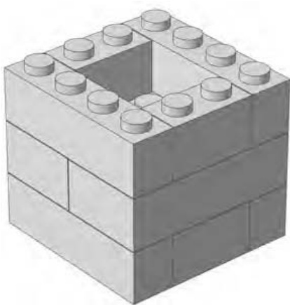
Figure 2-28: The hybrid column is both lightweight and self-straightening.
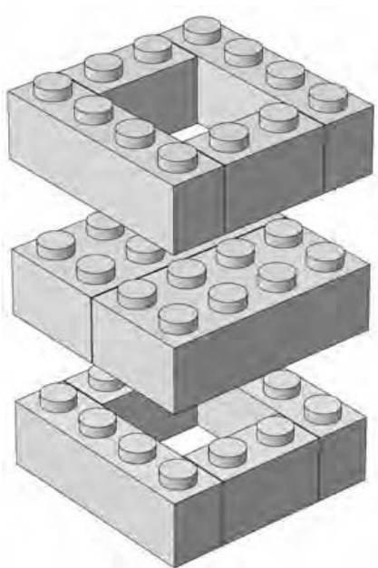
Figure 2-29: An “exploded” view of the hybrid column design showing the orientation of the different layers.
Given the actual inventories of bricks that most builders have, this version may be more realistic to build. It’s unlikely that you will build a large-scale model entirely of bricks or entirely of and bricks. In most situations, you are much more likely to mix and match all sizes of bricks as you need them. Therefore, when it comes to having bricks left over for your columns (bricks that you don’t need in the main model) you will probably have a good mix of the three sizes.
Remember that your models may not always be so large that they need internal bracing. But don’t discard some of the construction patterns you’ve learned while looking at columns and beams. In Chapter 3, you will see just how useful a simple post–style column can be when you go to create a small building. And you can use beams, apart from linking columns together, to support floors within a building or give you something solid onto which you can add a roof. Keeping the different patterns in mind gives you the essential tools you need to be a successful LEGO builder.
Review: Basic Building Principles
Now you have some idea of the best ways to connect bricks and make your models strong. It’s also important to understand how to plan your constructions. You want to build sensibly so that you minimize problems and enjoy your building sessions to the fullest. Here are a couple of basic principles that will help you do that.
1. Build big but think small.
No matter how big you think your model might end up, consider breaking the entire work down into smaller sections that are easier to work on. You’ll make the model seem less daunting and make it easy to figure out how to build very high sections or perhaps sections that are constructed at different angles than the rest of the model. For example, if you’re building a skyscraper, think about building sections of a few floors each, then attach these sections to each other.
If you’re making a model of a real life object, like a building or a vehicle, examine the object and try to find natural separations. This might be where the size or shape changes dramatically or where one color ends and another begins.
Existing separations can help you to determine how to build your model in sections. For example, if you’re building a pickup truck, you might want to build the cab separately from the box section.
2. Pick the right bonding pattern.
The decision of which of the three main bonding patterns to use (Figures 2-2 through 2-4) will vary from model to model and even within the same model. You won’t always want to use overlapping, despite its obvious strengths. Sometimes you will want to stack bricks and other times you will want to stagger them. Throughout the book, I point out which pattern you’re using and why. As a result, as you move on to designing and building your own models, you will have a better sense of the pattern you should use at any given time.
3
M I N I F I G S C A L E : O H , W H A T A W O N D E R F U L M I N I F I G W O R L D I T I S !
The LEGO system is always evolving with the addition of new elements, colors, and updated set designs that reflect the times. Perhaps one of the more significant additions to the system came in
1978 when the miniature figure,
better known as the minifig, was
added. The most basic version of
a minifig is shown in Figure 3-1.
Although it is really a collection of three pieces (legs, upper body, and head) the minifig typically arrives as two pieces (legs and upper body with the head already attached). Once you’ve built a set containing a minifig, you’ll probably leave it fully assembled, often with some style of hair or hat and sometimes with a tool or other accessory to hold in its hands.
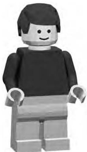
Figure 3-1: Who is this guy, and why is he smiling?
Over the years, I’ve seen many different types of minifig, with a wide variety of different styles and costumes—from astronauts and cowboys to helicopter pilots, racecar drivers, and many more.
Scale: It’s All Relative
No matter how big your LEGO collection is, you probably have a few minifigs lurking about. It seems only fair then that you look at building a world to their scale.
Simply put, scale is how you describe the relationship between the size of one object and the size of another.
But what is minifig scale? For simplicity’s sake, assume that from the point of view of the minifig, a minifig is, on average, about 6 feet tall—not the inches that you measure it to be. In Figure 3-2, you can see that your basic minifig just barely gets to that mark on a ruler.
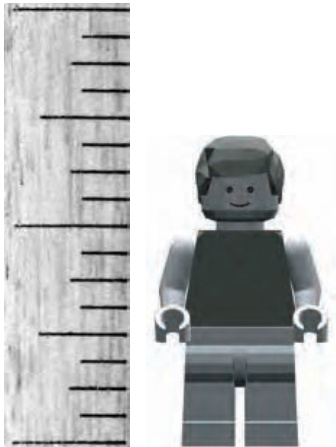
Figure 3-2: How does a minifig measure up? In our world he’s only an inch and a half. In his world he’s six feet tall.
Having made this assumption, you know that inches in the world of minifigs represents 6 feet in our world. Let’s take that information and figure out the scale.
Calculating Scale
To convert to minifig scale, do the following:
- First, convert 6 feet into inches. Because there are 12 inches in a foot, the calculation is pretty simple. 12 inches feet inches
- Then, divide your model/minifig height into your real height. 72 inches inches inches
In other words, this is the formula:
Height of same object in your world Actual model height Scale value
- Finally, create your scale. Your minifig is
1:48 scale (pronounced “one-forty-eighth” or “one to forty-eight”)
Scales are shown as two numbers separated by a colon. The number on the left represents one real object. The number on the right represents the number of scale objects it would take to equal the same size. (You may see scale written as a fraction, like , but the meaning is the same.)
This scale tells you that if you could stack 48 minifigs on top of each other, without having them tumble down, they would equal just about 6 real feet in height.
Figure 3-3 shows another even simpler example. A standard brick is shown to the right of a Duplo brick. These larger bricks are part of LEGO’s line of products aimed at younger children. By comparing these two pieces, you see an easy-to-understand example of a 1:2 scale. In other words, for every one Duplo brick, you need two regular bricks to equal the same dimension, because Duplo bricks are twice as high, twice as wide and twice as long.
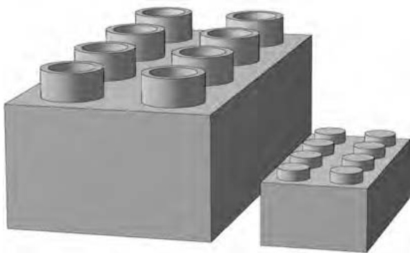
Figure 3-3: A standard brick and a Duplo brick help demonstrate the 1:2 scale.
Once you have the scale figure, you can use it to work backward, taking a real life object and deciding how big it should be in your minifig world. Let’s use an example of a house, because you know every minifig will want one or two. Let’s say that the house you want to use as inspiration is 24 feet tall in real life. This time you divide the actual height (24 feet) by your scale value (48).
24 feet inches (converted to inches so that your result is in those units)
It’s easy to see that your minifig scale house should be 6 inches tall in order to accurately represent the actual building you’re using as your guide.
From the Ground Up: Creating a Minifig-Scale Building
For many years, houses, police stations, hospitals, and other buildings were often used as inspirations for sets put out by LEGO. These days, sets with a town theme aren’t as common as they once were, but that shouldn’t stop you from making your own.
One thing that always makes official LEGO sets so interesting is the way the designers add architectural details to models of buildings. In the case of buildings, this may take the form of some well-placed arches over windows, a simple chimney rising from the roof, or perhaps some smooth tiles made to appear like sidewalks.
These techniques enhance what might otherwise be boring buildings and turn them into the vibrant places where minifigs like to live and work. When constructing your own models, you can use these same ideas to improve the realism and therefore the appeal of your LEGO town.
For the remainder of this chapter, we’ll focus on a single model built to minifig scale. I’ll use a small-town railway station as a platform upon which to demonstrate some of the principles you learned in Chapter 2. Starting from the ground up, I’ll show you the various parts that go into such a model and I’ll teach you how to apply those same building techniques to other buildings in your LEGO town.
As you read along, remember that this building doesn’t have to end up as a train station. You can adapt the basic design so it becomes an ice cream parlor, a hamburger stand, or maybe even a ticket booth for a theme park or a zoo. How you use it within your LEGO town is open to your imagination. You are never forced to color inside the lines when building with LEGO bricks.
Building Two Versions of the Train Station
To get the most out of this exercise, we’ll need to tackle the building from two perspectives. First, we’ll explore how you might build the building as if it were an official LEGO set created from a nearly unlimited range of parts. This way allows you to use specialty pieces to detail the model. Afterward, I’ll remake parts of the building using more common pieces, like those you might find in your own collection.
As you can see, I’ve based the design of the railway station on one you might find in many small towns across North America. A typical station constructed sometime in the late 1800s or early 1900s might look something like Figure 3-4.
Often, these buildings shared a number of common features. Low-angle sloped roofs, arched entryways, and windows dressed in contrasting colors are just some of the traits you can see on many such stations.
Before I can build the roof or any of these other details, I first need to construct the building itself. To do so, I will use a simple overlap technique for the outside walls before incorporating some slopes to complete the roof design.
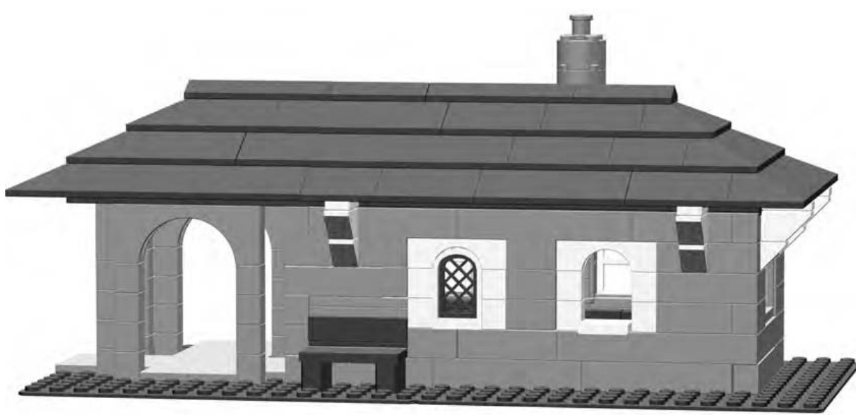
Figure 3-4: Your goal—use the design ideas for this building to create all kinds of structures for your LEGO town.
Bill of Materials: The Parts You’ll Need to Make This Model
Figure 3-5 shows you the Bill of Materials you need to build your own copy of this model. The term Bill of Materials is used to refer to a picture of all the elements you need to build a model and how many of each you need. Remember that you may not have every single piece indicated in the diagram, but that doesn’t mean you can’t build the model. For example, if you are short on bricks, why not replace each one of them with two bricks? Are you missing one brick in a certain color? Why not stack up three plates to make something that will serve the same purpose? Use your imagination to substitute one or more elements when necessary.
Step by Step: Train Station Construction Details
I’ve broken the instructions for building the train station down into a series of steps, each accompanied by a picture. Instructions that come with official LEGO sets use similar pictures to represent each building step, but they don’t usually have words to describe what’s happening. In this book, my main objective is to teach you about building with LEGO—why you should use certain parts and when to use certain construction techniques. By explaining each step along the way, I hope to give you a better sense of what’s going on in the picture for each step. That way you’re not just following along, but you’re also learning how to eventually create your own models.
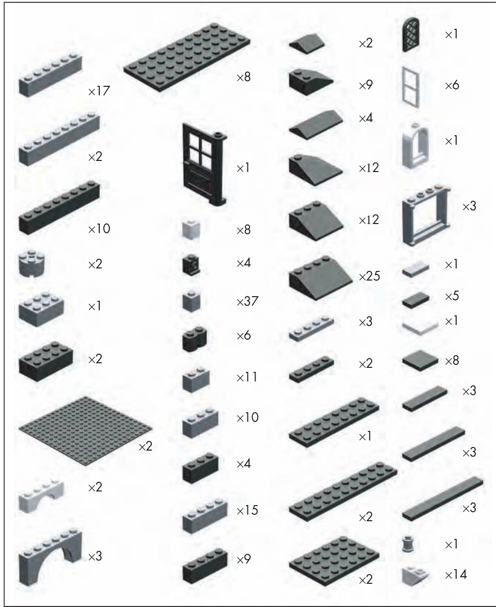
Figure 3-5: The Bill of Materials for the train station model
Step 1
In Figure 3-6, you might notice some bricks to the left side of the building. As the building goes up, you’ll find that I’m using the stacking technique to create very slender columns based on the simple post technique from Chapter 2 (see Figure 2-24). When I’m done, there will be six of these columns, and they’ll support part of the roof. Individually, these columns are very weak versions of the column technique. However, when you use them together, and support them with arches, as you’ll soon see, they represent a reasonable balance of form and function.
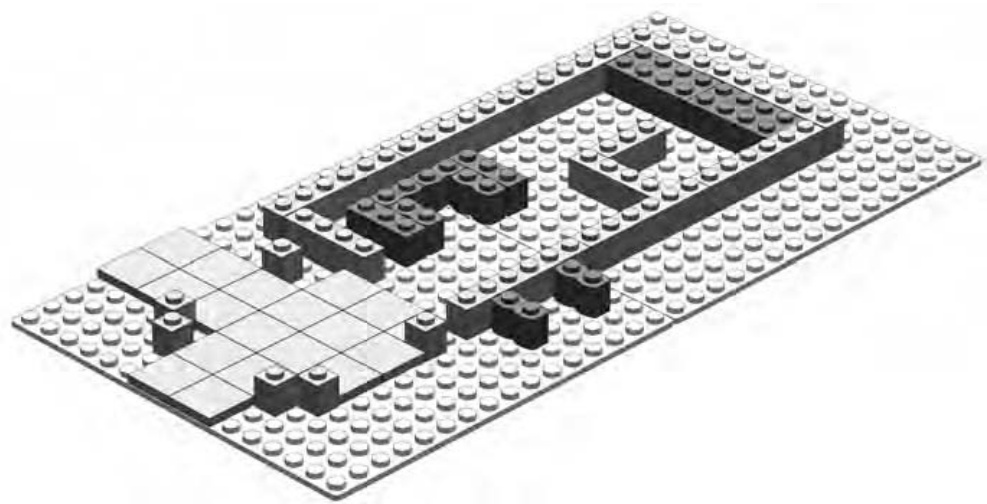
Figure 3-6: Every structure needs a good plan. The layout of your foundation contributes greatly to how the building ultimately looks.
Step 2
In Figure 3-7, you can see what happens after I add the second course of bricks. As promised, this figure shows that I’m using the overlapping technique for the main walls and the stacking technique for the columns.
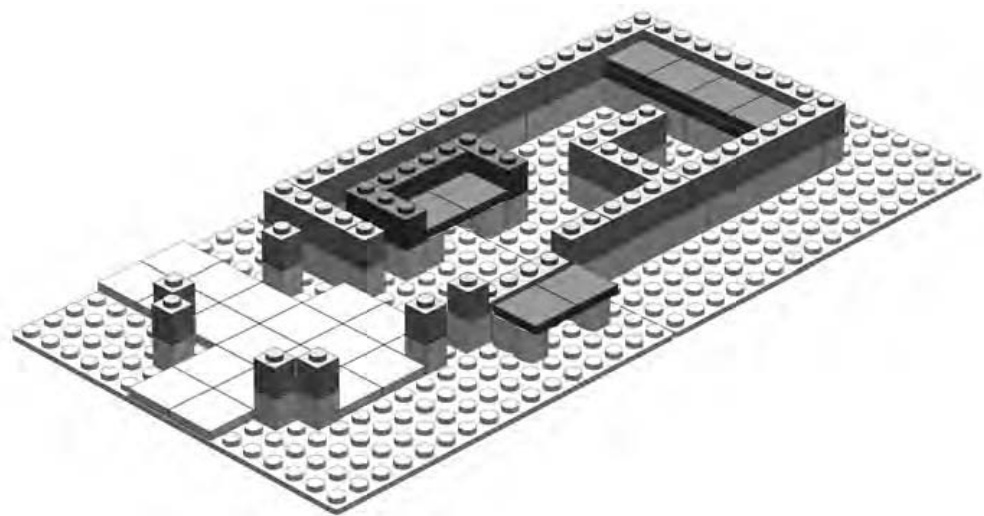
Figure 3-7: Overlapping and stacking techniques used effectively within the same model
Notice how I’ve applied the overlapping technique to what will become the counter inside the station—the L-shaped wall near the top right of the model, as shown in the instructions. This wall connects to the outside wall with a brick and that makes sure it doesn’t go anywhere when the train rumbles by on the track.
You can also see three benches. The first is outside the station; it sits on two log bricks. The second, inside the station, has armrests. The third, at the very top right of Figure 3-7, is a long bench seat that minifig children can sit on to watch the trains coming along the track.
It’s usually best to add things like furniture or inner walls early on in the building process. That way you do not have to take apart the walls or roof to add them later.
Step 3
Next, as the walls and columns continue to rise, I need to install the large windows, as shown in Figure 3-8. It’s important to think ahead and decide early on where walls will meet, where windows will be located, and which wall will have the opening for the door. This train station design I’ve provided you with takes care of all of these.
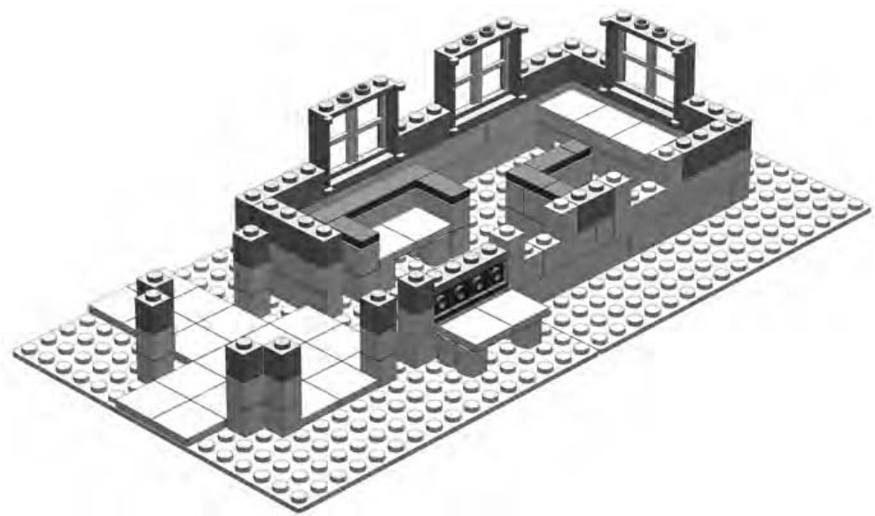
Figure 3-8: The model begins to come to life as the windows are added.
Don’t panic if you don’t have windows like the ones in Figure 3-8. I’ll show you other ways to create the same effect later in the chapter.
Near the center of Figure 3-8, you see four studs facing outward, just behind the bench I’m building there. You’re looking at four headlight bricks lined up in a row. These are one of the specialized elements found in the Brickopedia (see Appendix A). Each of these bricks has a traditional stud on top but also has a stud on one side. You’ll see how I put these to good use in the next step.
Step 4
As you can see in Figure 3-9, things are shaping up. The door is in place and ready to keep waiting minifigs warm while they wait for trains to arrive and depart. I’ve also added a small, arched, nonfunctional window with a latticework screen, just to the right of the outside bench. The opening to its right is where the ticket agent can serve minifig customers. The tile sticking out from this opening is meant to represent the counter of the ticket window.
In Figure 3-9, I complete the outside bench, using headlight bricks to do so. I cover the fronts of the bricks (where the studs face outward) with the tile; this forms the backrest for the bench. This simple example showcases the additional building techniques you can employ when you’re building with pieces from the specialized elements category (discussed in Chapter 1).
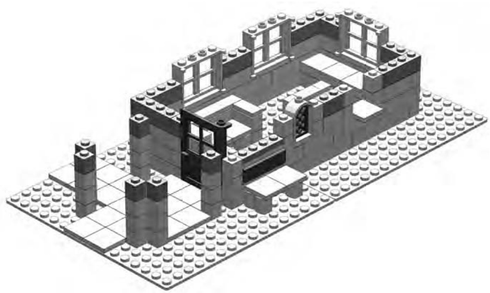
Figure 3-9: Windows and doors add life and realism to your buildings.
Step 5
Figure 3-10 shows how I can add arches to join pairs of columns together. In architectural terms, such an area is referred to as a colonnade —a series of columns sometimes used to support a roof structure. These columns do just that, as you’ll soon see.
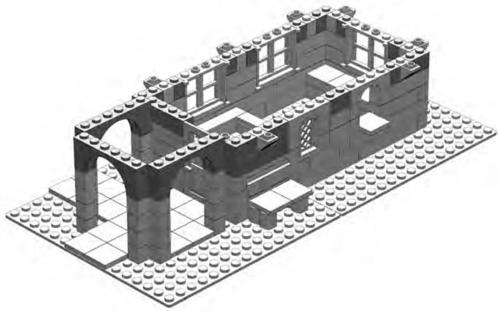
Figure 3-10: The purpose of the columns becomes apparent as you add the arches.
Now that the outside walls are almost complete, notice that the two windows at the front now sport arch bricks above them, providing a classic look. Also, for this section, I’ve gone back to the stacking technique for the small section between those two arched windows. I decided on this move because I wanted to create the appearance of frames around the windows. In reality, the frames might have been painted in a color different than the rest of the building. (See the end result in Figure 3-4.)
NOTE To get an even better idea of how you can use color in a decorative way, visit www .apotome.com/instructions.html and see the train station in its original red and white color scheme.
Step 6
Now I’ll add the second set of inverse slopes that help create the effect of arched supports for the roof, as shown in Figure 3-11.
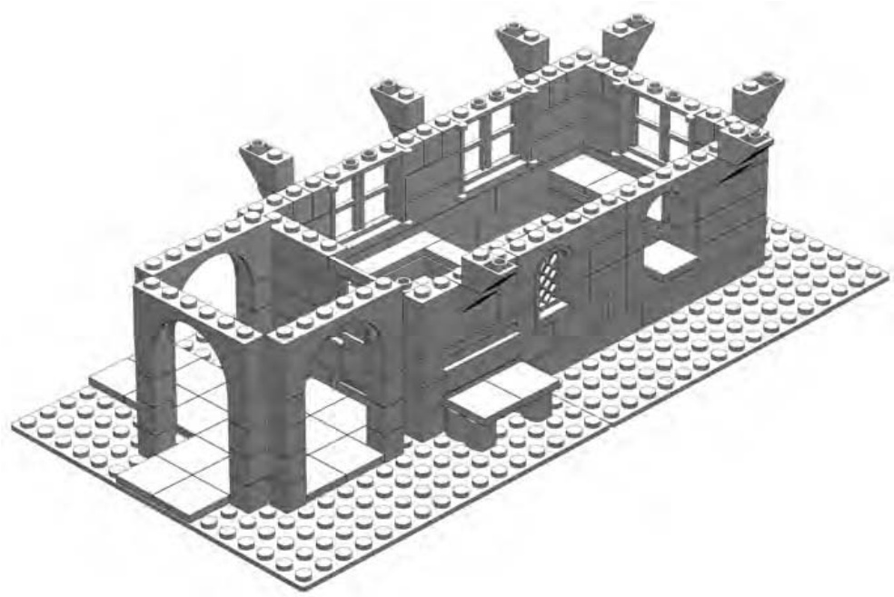
Figure 3-11: The inverse slopes get ready to pretend they are supporting the roof.
Although an inverse half-arch piece does exist in the LEGO system (see the Brickopedia), its dimensions weren’t suitable in this case because it would have stuck out past the edge of the roof by one stud. By building your own arches out of slopes, you can produce exactly the look you want.
Step 7
Note how carefully I select the bricks for the top course, as shown in Figure 3-12. Where possible, you must try to tie the lower courses together by making sure that the top layer overlaps as many seams as possible. Consider, for example, the brick above and between the two arched windows. That brick is critical to making sure the ’s between the windows don’t tumble in or out of the building. (Remember, as we discussed in Chapter 2, it’s okay to stack bricks as long as you eventually add something to hold them together.)
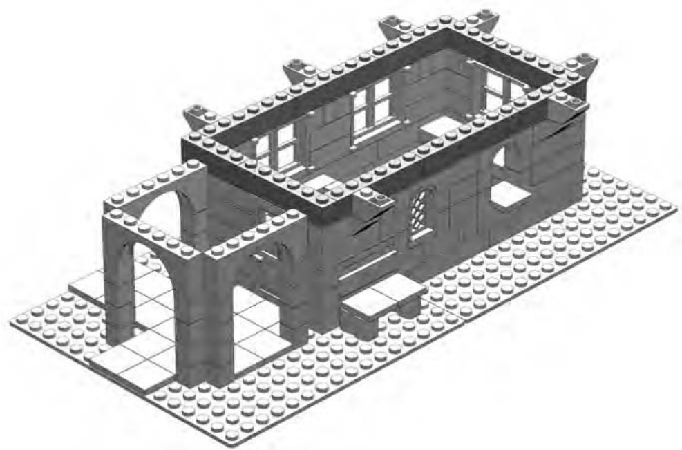
Figure 3-12: Be sure that all the lower layers are stabilized with stretcher bricks along the top course.
Another good example of overlap can be seen in Figure 3-12 when you look at the that sits over the door to the building. The door needs some thing upon which to hinge. In addition, that brick connects the walls on either side of the door.
The opening for the door is something that weakens the walls, not allowing them to interlock. The above the door helps restore some of the integrity by holding the walls in place.
Step 8
A roof at last! Well, at least for the colonnade. In Figure 3-13, I begin adding the roof, but not to the entire building. This is a special feature of this design that I explain in the next few steps.
To prepare for the addition of this function, I place a series of tiles around the top of the main walls and on the tops of the faux half arches.
In Figure 3-13, the plates over the colonnade appear dark gray. In the original design of the building, they were black. For the purpose of actually building the station, they can be just about any color you have on hand. Light gray, brown, tan, or even white would all work fine for these pieces. In the next step, you just cover them up with roof bricks anyway. The plates make up a support structure and are not at all decorative or even visible in the final model.
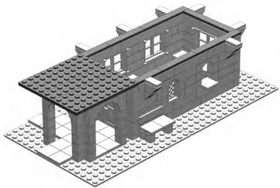
Figure 3-13: Part of the roof and lots of tiles. We’ll see the reason for the tiles in just a few more steps.
Step 9
Slopes make such good elements for making roofs that they are sometimes called roof bricks. For this model, I use 33-degree slopes extensively to give the roof the gentle angle I want. I begin the first layer of roof pieces by adding them onto the plates I added in the last step. You can see what I mean in Figure 3-14.
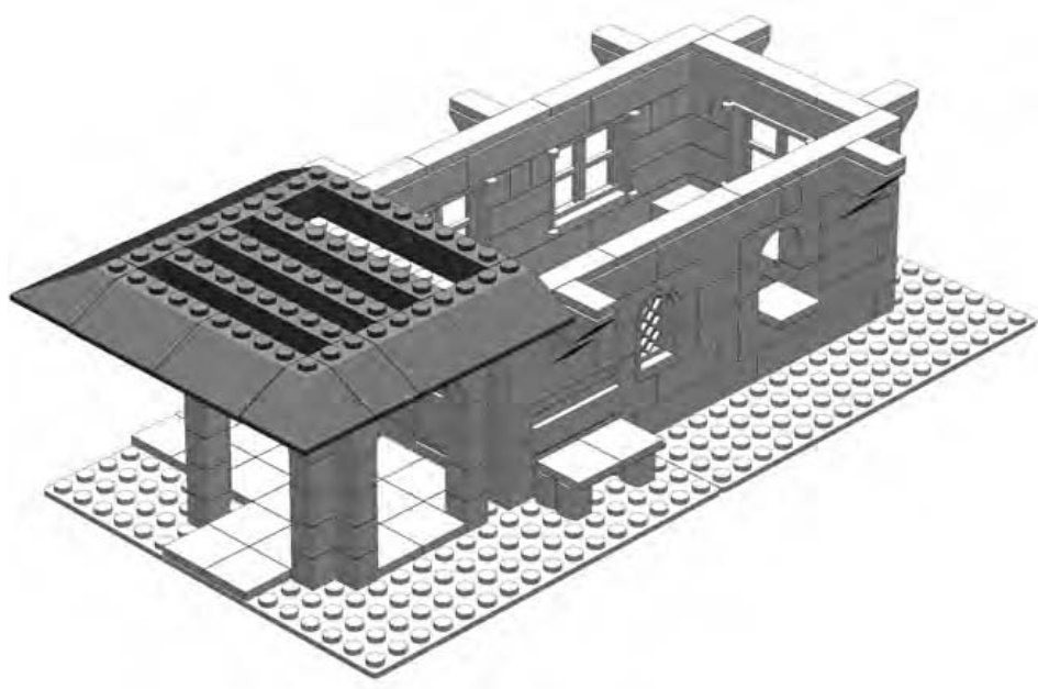
Figure 3-14: The rest of the roof is yet to come. For now, focus on the area directly above the entranceway.
Wait a minute, only half a roof? That might be the question you’re asking by now if you’re looking at Figures 3-14 and 3-15. Here, I’m creating a nicely sloped and very functional roof, but only for part of the station. This is intentional and helps turn this project into something that you can use as a static display or as a play set. The tiles along the top of the main walls play an important role in creating this dual functionality.
In Figure 3-14, you can see that the lowest layer of slopes extends from the sides of the building out to the same distance as your faux half arches. When I get to the end of the model and reveal the secret of the roof, you’ll see that although they aren’t really attached, the inverse slopes will appear to support the roof. Here, I’ve used LEGO bricks to simulate the look of a real life object without recreating its actual function.
Step 10
As I add the next layer (see Figure 3-15), I’m making sure to overlap the slopes, just as I did with the bricks I used to create the walls.
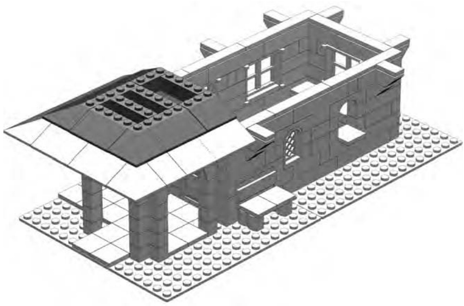
Figure 3-15: The second course of 33-degree slopes
The three bricks that I added in Figure 3-15 serve the same purpose as the bricks I added in Figure 3-16. They provide support for the layer of slopes above them, which I’ll add next.
Step 11
Remember that color isn’t everything. Although I intended this building to have a black roof, you may not have those parts in that color. Red or blue slopes work just as well, and you can change the colors of the walls to match. In real life, old buildings are often repainted in colors other than those they were originally. LEGO models are no different; don’t feel restricted to what a book or an instruction manual suggests. Experiment with different combinations of colors based on what you have in your collection or even just the mood you’re in while you’re building.
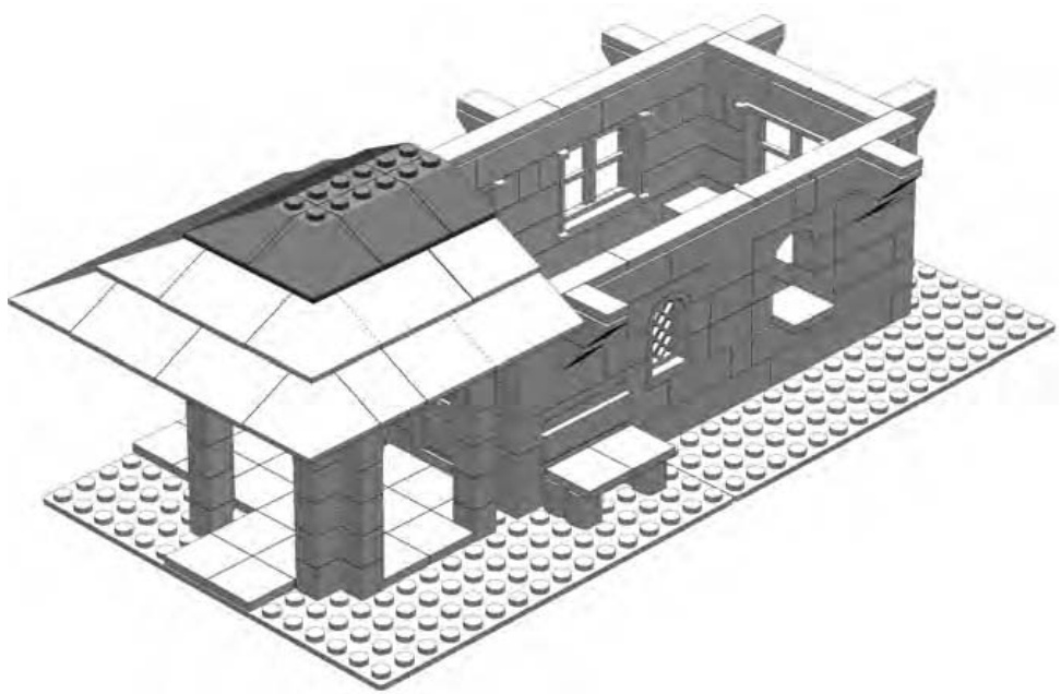
Figure 3-16: Nearly there. The graceful pagoda-style roof takes shape—at least some of it!
Figure 3-17 shows the completed main model. What follows in the next section is a submodel—one that helps complete the main building.
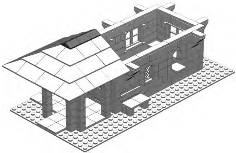
Figure 3-17: Peak elements cap this section of the roof.
A submodel is a group of pieces that you assemble apart from the main model. For example, you may build the wings of an airplane separately and attach them to the body at the end of the building process. Or you might put together some pieces that then become the engine for a car. Once you have completed the body of the car, you add the submodel (in this case, the engine) as a single unit, made up of the group of parts you have used to assemble it. In the case of your train station, I’m going to build the larger section of the roof as a submodel.
As you may have guessed by now, the larger part of the roof will be removable. Sometimes you will want to have access to the inside of your LEGO buildings so that you can help your minifigs go about their business. One way to achieve this is to have a building that splits in half and opens up like a dollhouse. In such a case, you can get to the interior of the building from the open sides. The design I’m using here allows you to pull off part of the roof and see the insides from above instead. So watch as I build the rest of the roof and see how it’s going to look.
Submodel: The Train Station Roof
Another reason you may want to occasionally use submodels is to eliminate the need to include them in the main instructions.
This roof submodel is a perfect example. The first step in making this submodel involves starting off with some pieces flipped upside down (Figure 3-18). Having that step included in the main instructions may have lead to a bit of confusion, so it’s better to handle this part of the roof as a separate unit—a submodel.
Step 1
The roof submodel is exactly the same width as the portion of the roof we already build on one end of the main model. The length of the roof submodel is the same as the opening we left above the main part of the railway station. In other words, when it’s finished it will perfectly match up with the main model and form a complete roof. In Figure 3-18, I start with some plates facing studs down.
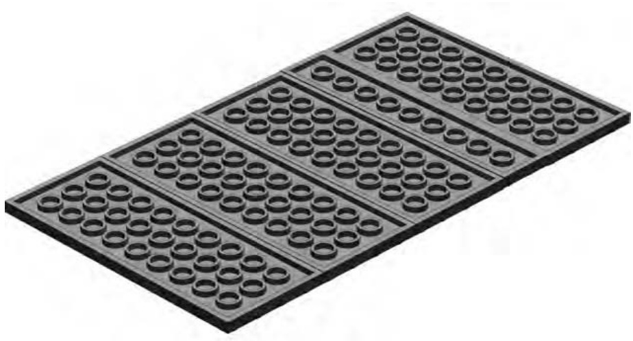
Figure 3-18: No, your book isn’t upside down; the plates are turned studs down.
Step 2
In Figure 3-19, it’s easy to see the positioning of the next course of plates (now shown in dark gray). If I’d put these plates down first, it would have been trickier for me to properly show you how to position the next layer.
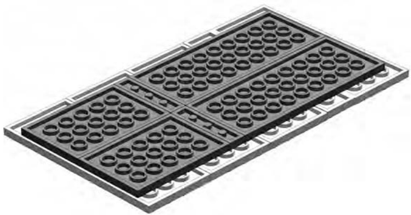
Figure 3-19: By starting out with the plates studs down, it’s easier to place the first course of plates.
Step 3
Once I get through the first two steps, I turn the plates right side up. Notice the direction that each layer of plates is turned. The two layers should have the long sides of the plates placed perpendicular to one another. This is another form of the overlapping technique, where long pieces are placed at right angles to each other. In the case of plates such as those shown in Figure 3-19, this type of overlapping creates a very strong base upon which to build another part of the model.
In Figure 3-20, you can see that I begin adding the slopes to form the angled part of the roof.
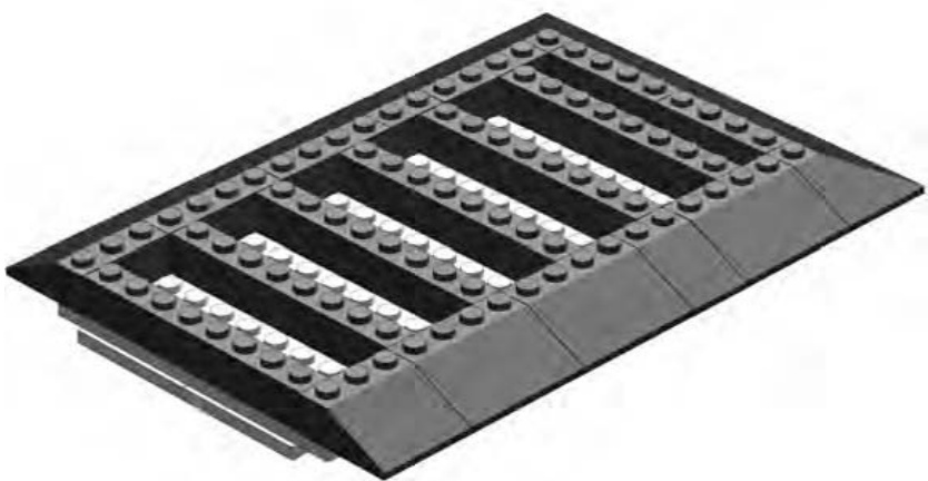
Figure 3-20: Flip the plates over, and then start adding slopes around the edges. The bricks in the middle set the stage for the next layer.
One idea I hit upon earlier in this build is that of planning ahead. In Figure 3-20, you can see that I’m already thinking of the next layer of slopes and how they will connect. They will overlap not only the bottom layer of slopes, but also the bricks running through the middle. As always, this adds strength to the model. These ’s provide another form of bracing. Also, by not making the inside of the roof a solid mass of bricks, I save weight and, of course, bricks!
NOTE The inner five bricks can be any color you have handy. You won’t see them once you’re finished.
Step 4
In Figure 3-21, I add a second layer of roof bricks. Notice the standard bricks in the middle. I’m using them, like the ’s below them, as a support system for the layer that will be added above them.
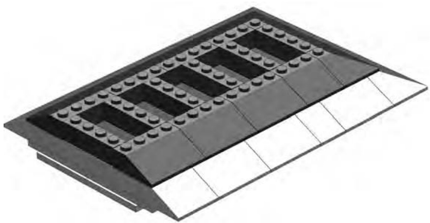
Figure 3-21: bricks play the same role as the below them.
Step 5
One big part of a successful LEGO model is that every layer or substructure works together to produce the final result. In Figure 3-22, you can see a brick that seems to stick out among the slope bricks in the layer. This isn’t a mistake; it sets the stage for pieces I will add in the next step. This example shows one layer working together with another to create the effective model I’ve been talking about.
Step 6
As promised, Figure 3-23 shows you why I added that brick in the last step. This becomes a solid platform upon which to build the remainder of the chimney. The peak elements, also added in this step, cover up part of the brick and make it appear to simply rise from the inside of the building, just like a real chimney would.
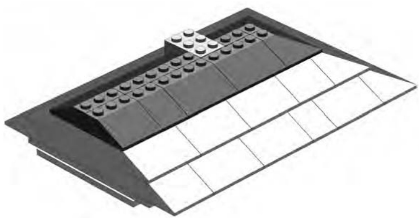
Figure 3-22: Prepare a place for the chimney.
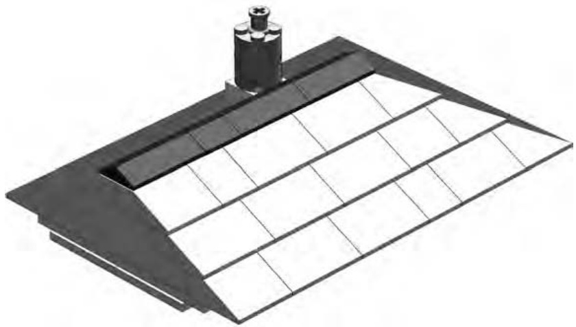
Figure 3-23: The submodel is now complete. Try placing this roof section onto the rest of the model. The result should look just like Figure 3-4.
Don’t forget that if you don’t want to use this building as a train station, it can serve many other functions. In addition, you can apply the building techniques you used throughout this chapter to any other model you create.
Substitution: When Other Parts Will Do
By this point, you might be saying to yourself, “I’d like to build a station like that, but I don’t have all those special pieces.” Don’t worry! You can replace certain specific pieces with other more common pieces. This is a design technique known as substitution. It has nothing to do with replacing French fries with mashed potatoes, but it has everything to do with making the best use of your existing LEGO pieces.
Although you might not be able to make an exact copy of this model with your own collection, you can come close by substituting pieces where needed.
Substitute Walls
Even if your collection comes mostly from assorted buckets, you should have enough basic bricks to make the walls the way they appear in the first model. You may not have exactly the right number of pieces in the same colors, though, so don’t be afraid to change colors. Gray, brown, or even white would all be reasonably realistic colors.
Substitute Arches
It’s often possible to build an arch from inverse slopes. To do this, you first need to determine the slope, or curvature, you are trying to imitate. To get the slope, you use a combination of the rise and the span.
Imagine the span as the length of an imaginary line that runs from the bottom inside edge of one side of the arch to the opposite side. Then, imagine the rise as the distance from this line to the center underside of the arch itself (also known as the soffit), as shown in Figure 3-24.
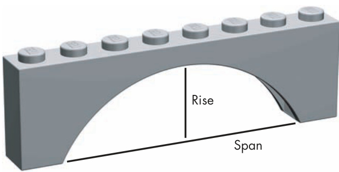
Figure 3-24: The two most important parts of an arch
It’s easy to see that by increasing the span of your arch, you are stretching it out sideways, and therefore, you’re lowering the angle at which the curve of the arch extends across the other side. This can be a useful shape for things like bridge construction.
Similarly, you can visualize that if you increase the rise of the arch, the angle from the base of one side to the point at which the arch peaks will increase as well. High narrow arches are commonly found in doorways or as part of building facades.
Typically, when I am trying to replicate an arch with slopes, I use a photo or a sketch of the structure as a guide. I then hold up inverse slopes to the picture and try to match the angle of the arch with the angle of the bricks. You can see in Figure 3-25 that by choosing carefully and sometimes mixing different angles of slopes, you can make some handsome arches without using a single arch brick.
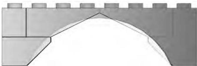
Figure 3-25: A standard arch is shown superimposed over top of a composite arch made up of and inverse slopes. The result is nearly the same shape.
Additionally, you may wish to insert standard bricks or plates between the layers of the slopes to increase the rise of the arch without affecting its span.
Substitute Windows
Windows can sometimes prove frustrating, because they aren’t always as easy to come by as one would hope. By using some simple tricks, however, you can give your station its own characteristic windows. Figure 3-26 shows that by simulating a small arch (replacing a arch element), I’ve created a look similar to the original train station model in Figure 3-4.
To replace the windows on the side and end of the station, try the trick shown in Figure 3-27. It’s not perfect, but it’s better than no windows at all.
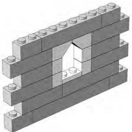
Figure 3-26: You can replace the arches used in the original design with inverse slopes.
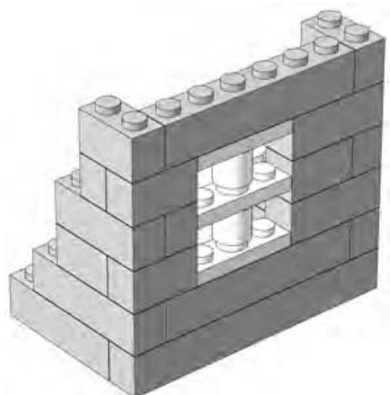
Figure 3-27: Substitutions won’t look exactly like the pieces they’re replacing, but searching for combinations that work is half the fun.
In Figure 3-27, you can see that the thickness of a standard plate has again been put to good use. Here I use three plates separated by two cylinders. The result is a window that is three bricks high and that fits perfectly where I need it.
Substitute Roofs
Finally, you might need another way to create a roof. What you may find when you search your collection is that you have sloped roof bricks, but they aren’t the black color shown in the first version of the model. If this is the case, you can easily substitute red or blue slopes for the black ones and still maintain the same style of roof. Or, you may find you just don’t have enough slope bricks of any color and need another way to make your roof.
In the next example, I use common bricks to create the illusion of a sloped, though somewhat jagged, roof. I do this by setting down a layer of bricks that mimics the length and width of the sloped roof. As with the original, I am sure to include internal bracing in the form of longer bricks that run from side to side. (These are not unlike the ceiling joists found in real buildings.)
Next, I carefully add the second layer, making sure to overlap any point at which two lower-level bricks come together. By moving each layer inward by three studs, I come close to simulating the slope originally created by the 33-degree roof bricks. I am effectively combining the overlapping and staggering techniques in this process.
You can use this example (shown in Figures 3-28 through 3-33) to replace the steps shown in Figures 3-13 through 3-17.
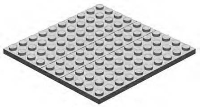
Figure 3-28: These are the same plates you see in Step 8 of the main model (Figure 3-13). Begin building your substitute roof from that point forward.
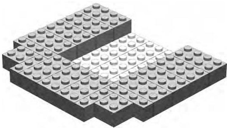
Figure 3-29: Instead of slopes, I used standard bricks.
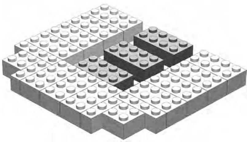
Figure 3-30: The three bricks in the middle will help support the next layer.
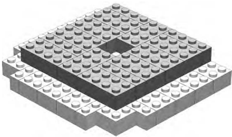
Figure 3-31: The second layer is staggered from the first. This provides the imitation slope for the roof.
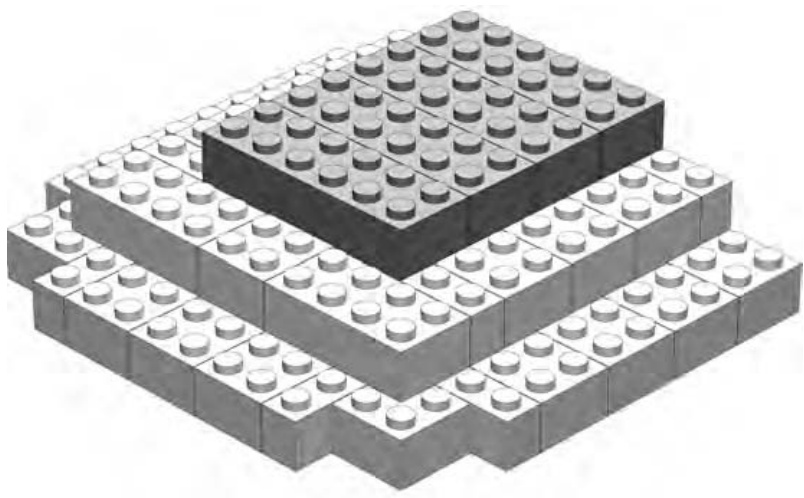
Figure 3-32: bricks hold everything together at the top.
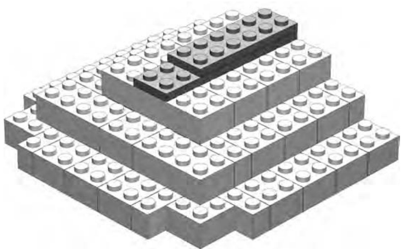
Figure 3-33: The plates overlap, and help hold together, the bricks from the previous step.
You can create the larger part of the roof (the submodel) using this same technique.
Another way to create simple sloped-roof structures is to attach ordinary plates ( , , and so on) to hinged elements and then angle them as you like. Figure 3-34 shows a simple example of this technique.
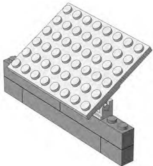
Figure 3-34: Roofs made from hinged plates can be angled at any pitch you need.
The brick hinge is a wonderfully useful element. It comes in two varieties. The version shown in Figure 3-35 has a plate as the hinged portion. It is also available with a plate on top.
Pieces like the brick hinge allow you to add varying angles to your models that wouldn’t be possible with just standard bricks and plates.
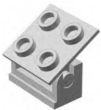
Figure 3-35: The brick hinge
If you want to use the brick hinge and plate technique, it’s important to plan ahead and build the hinges into the top of the wall. The spaces between them are filled with two plates (shown in Figure 3-36) because a full-height brick would hit the underside of the roof plate.
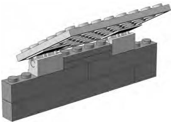
Figure 3-36: A hinged roof can be easily opened so that you can peek inside your building if need be.
Review: Building Techniques and Alternatives
The train station model presented in this chapter helped us look at some very basic building techniques as they apply to a minifig-scale structure. It showed that the overlap technique, which I first demonstrated in Chapter 2, is one of the most fundamental principles when it comes to successful LEGO models. You will use it time and again throughout just about every model you build. Although stacking and staggering are important also, it is the overlap method that best creates strong bonds between LEGO elements.
The main model in this chapter also demonstrated substitution on a couple of different levels. The building itself, as I pointed out early in this chapter, can be used for any number of different roles; it doesn’t have to just be a train station.
The various sections of the building also provided examples of substitution. And although the alternate roofs, windows, and arches don’t look quite as realistic as the “official” version, they do offer some flexibility. For example, a proper arch brick can only ever be a certain size and shape. On the other hand, your slope-derived versions can grow or shrink as you need them to. So although the improvised version of the train station might not win awards for its looks, you can certainly use it to add character to a LEGO town with just the bricks you have at hand.
This principle—substituting one technique for another—is something I’ll hit on again throughout this book. Remember that substitution isn’t a single technique. Rather, it’s a way of looking at a problem and (in the case of LEGO models) finding an alternative part or bunch of parts that can provide you with a solution when the “right” parts just aren’t available. It serves to remind you just how flexible and creative the LEGO system can be. You are never stuck with just one way of doing things or just one particular element that you need to use. Your imagination and alternative pieces are all you need to solve most building problems.
4
M I N I L A N D S C A L E : T H E W H O L E W O R L D I N M I N I A T U R E
In 1968, something spectacular happened in Denmark: an entire new world was created. That was the year the LEGO company opened a very unique theme park, called LEGOLAND, not far from its headquarters.
NOTE Denmark is a small Scandinavian country located north of Germany and Poland, bordered by both the Baltic and the North Seas. It is the country in which LEGO was founded in 1932, and it remains home to the company’s corporate headquarters.
Along with rides and snack shops, LEGOLAND also contained an incredible group of LEGO structures. This part of the park became known as Miniland. In the early days of the park, these Miniland creations replicated— at scale, of course—many famous Danish landmarks and buildings. Later, as the company opened other theme parks in more countries, new Miniland structures were built, modeled after other cities and structures from around the world. In Figure 4-1 you can see an interesting scene captured at LEGOLAND in Carlsbad, California.
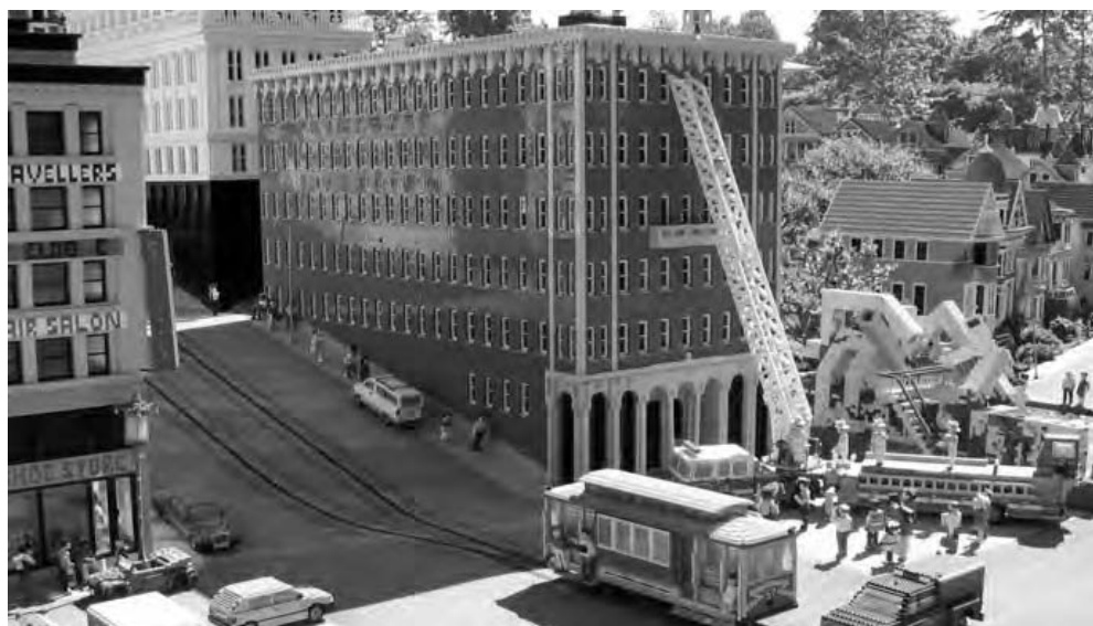
Figure 4-1: Don’t worry: things aren’t as bad as they seem. This fire truck is only a couple of feet long, its ladder is just under 3 feet tall, and the people in the scene are each less than 4 inches high. The details are what make it look very real. (Photo by Tim Strutt, Ottawa, Ontario, Canada. Used with permission.)
Interestingly, even though miniland scale is used extensively in the LEGO parks, you won’t really find any official LEGO sets that contain miniland-scale characters. Equally notable is that unlike the very specialized pieces that make up any given minifig, miniland people are most often created from a variety of reasonably common LEGO elements. They may have parts such as inverted slopes for legs, plates for arms, or even cylinder plates for eyes.
Miniland Scale: Bigger but Still Small
In the last chapter, I talked extensively about the idea of scale and how it related to minifig models. I had you work out that minifig scale is around 1:48. However, the concept of scale doesn’t go away when you’re talking about miniland models; instead, the numbers just change.
Most of the miniland-sized models at the LEGOLAND theme parks are built to a 1:20 scale. This means that an average character (such as the fireman shown in Figure 4-2) is about 3.5 inches tall. Hopefully, this explanation helps you understand an important point about scale. As the number on the right (the scale value) gets smaller, the model you are making gets bigger. Therefore, the 1:48 minifig characters are about 1.5 inches high, whereas the 1:20 miniland figures are more than twice as tall.
Although miniland figures may be a bit blockier looking than their minifig counterparts, you can build them with more interesting costumes and poses, as you’ll see later in this chapter.
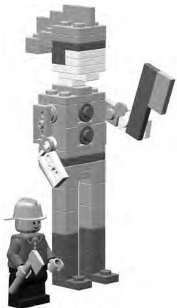
Figure 4-2: A minifig fireman and a miniland version of a similar character. The miniland man is two and one-half times as tall as his smiling minifig counterpart.
When building with minifigs, you mix and match their torsos with various legs or you give them different hairpieces and accessories. In the end, however, most minifigs end up looking somewhat similar. When you build your own miniland figures, the range of characters you can create is virtually unlimited. They will never be exact replicas of minifigs and will end up with their own unique features.
Creating a Basic Miniland Figure
You can build miniland figures in an almost endless variety of poses and outfits. Before you go crazy trying to accomplish all those possibilities, however, let me first show you a no-frills figure (see Figure 4-3) so you can get a sense of how these little folk are constructed.
This figure’s outfit (or lack thereof) doesn’t really tell you what he does for a living, and he’s not in any sort of action pose that lets you know what he might be doing. For now, just study his simple form so that you can get an idea of what building techniques I used to create him. I’ll give you instructions to build your own miniland character a little later in this chapter.
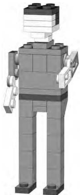
Figure 4-3: Like a department store mannequin, this figure is just waiting to be attired in any number of outfits.
First of all, take a look at his head. The head is square and a bit boring, as you can see, but don’t worry: I’ll show you how to add details later that take away some of that blocky feeling. Notice that the head is centered over the shoulders using a very simple technique; I’ll also describe this technique in a bit.
Now take a look at the torso, which is essentially two studs by three studs in size, though it is made up of several smaller pieces. After all, you need to make sure you have somewhere to attach the arms, and you also need to allow yourself the ability to create costumes by varying the colors of bricks and plates.
The arms, attached at their normal location, are just hinge plates, and in this example, there are not really any parts that represent hands.
Here, the legs are perhaps the simplest part of all. They are really nothing more than standard bricks with inverted 45-degree slopes for the hips.
The Best Bits: Useful Pieces for Miniland People
Although no LEGO element should ever be considered useless, it’s also true to say that, in some circumstances, some pieces are more useful than others. Tables 4-1 through 4-3 list parts I used to create the basic miniland figure in the previous section. You might find that these are the most handy to start out with. Think of the contents of these three tables as your toolkit for creating these little people. You may not use each piece in every figure you build, but these do give you a sense of the types of pieces you might want to gather before you start working on this type of model.
Small plates, like the ones shown in Table 4-1, are the key to creating the details of the head and neck.
Table 4-1: Small Plates for Making Miniland-sized Heads
| 1x1 plates | 2x2 plates | ||
| 1x2 plates | Offsetplates |
Technic bricks, like those shown in Table 4-2, are used to create the mechanism by which the arms are attached. The clip plates—used as hands—are optional.
Table 4-2: Assorted Pieces for Making Miniland-sized Torsos
| 2x3 plates | 1x1 cylinder plates | ||
| 2x3 bricks | 2x2 plate hinges | ||
| 1x2 Technic bricks | 1x2 clip plates |
Changing the slopes and bricks you use for the legs can help create different costumes for your characters. The examples in Table 4-3 are good choices.
Table 4-3: Various Pieces for Making Miniland-sized Legs
| 1x1 cylinder plates | 1x2 plates | ||
| 1x1 cylinders | 1x2 inverted 45-degree slopes | ||
| 1x1 bricks | 2x1x3 standard and inverted 75-degree slopes |
As you begin to blend the basic techniques with your own flair, you will undoubtedly find that you are mixing up how the head attaches to the body and how the legs are connected and positioned. Much like other such lists in this book, this list just gives you guidelines that are only intended as a jumpingoff point for your own creativity.
Basic Miniland Figure
You saw a picture of a basic miniland-scale character in Figure 4-3. Then, in the last section, you saw some of the most useful LEGO elements for creating these whimsical people. To get you started building your own cast of characters, I’ll show you six easy steps you can use to make a basic version of this type of model. From there, you can explore the variations on hair, outfits, and poses that I’ll talk about in the following pages.
Figure 4-4 shows you the first three steps to follow. I haven’t included a Bill of Materials for this model, but by looking at the toolkit I provided for you in Tables 4-1 through 4-3 and the steps themselves, you should easily be able to figure out which pieces you need.
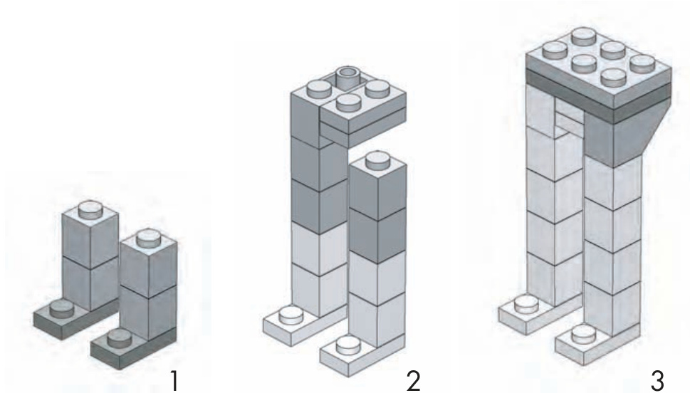
Figure 4-4: Steps 1, 2, and 3 for creating a basic miniland character
Notice that in steps 1 through 3 (Figure 4-4), I have added more than one layer of parts per step. Because this is such a small model, it’s easy to understand instructions like this. They help save steps by instructing you to add several pieces, at different layers, all at once. I use this same technique with steps 4 through 6 (Figure 4-5).
One interesting feature of this basic miniland figure is that you can pose the arms at any angle you like. Note in Figure 4-5 (steps 4 and 5) that the hinge element, representing the arm, simply sticks into a cylinder plate that itself is stuck into a Technic brick. There is just enough friction between the stud (on the hinge) and the cylinder plate to hold the arm up just a little or even straight up in the air! The head, as you can see in steps 4 and 5, is centered on the torso thanks to a single offset plate.
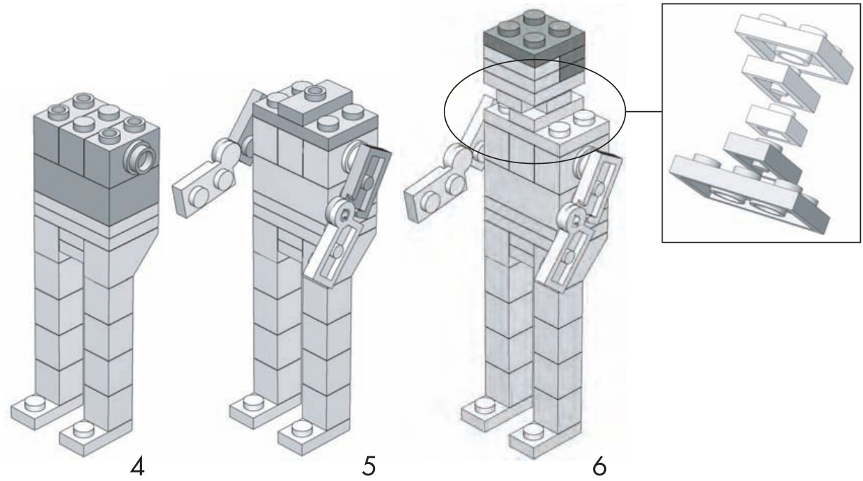
Figure 4-5: Steps 4, 5, and 6 for creating a basic miniland figure
Mix-and-Match Parts
You just saw how to create a very basic version of a miniland person. Now it’s time to make that character come alive by adding some additional details. In this section, you’ll examine various ways to create not only heads, arms, and legs, but also clothing and accessories to match. The following categories are similar to the toolkit I detailed earlier, but they differ slightly in how the figure is broken down.
Once you get the hang of building these parts separately, you can use different combinations of them to create your own world of miniland-sized people, each with a unique personality. Where possible, I’ll try to draw on pieces I included in the toolkit I provided earlier (Tables 4-1 through 4-3).
Heads and Hats
By now, you may have noticed that the faces of miniland people are somewhat abstract; they have no eyes or nose to speak of. In fact, their entire composition is really just representations of a person, not the hands, movable arms, and detailed faces that you see in the minifig world.
Therefore, creating a “face” for your miniland person becomes a matter of trying to suggest where the skin is located and where things like hair and hats begin. In Figure 4-6, I isolated the elements used to create the impression of a face and neck. Use whatever color plates you like in these locations to make each character unique.
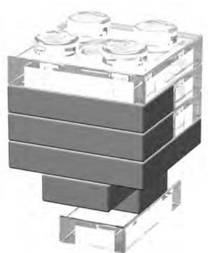
Figure 4-6: The solid elements represent the character’s face in this figure; the clear elements represent the character’s hair or hat, and perhaps its neck. Use different colors of plates to create realistic skin tones for your miniland folk.
You can also experiment with combinations of plates, cylindrical plates, and other parts, like the plate with studs to create items like hats and hair for your miniland people. In Figure 4-7, you can see that the head in the middle appears to be wearing a baseball cap, whereas the head on the far right looks like someone who’s good with a curling iron.
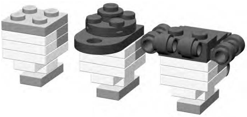
Figure 4-7: A basic head on the left, a capped head in the middle, and a head full of curls to the right
Shirts and Skirts
In the toolkit I provided earlier in this chapter (Tables 4-1 through 4-3), I broke down each figure into its head, torso, and legs. Of course, in reality, you might be building an astronaut who wears a suit that covers the entire body. Or, your figure might be a lovely lady in a dress where again, you would want to consider the torso and the upper-leg design together. This section looks at how to dress a character.
You give the impression of a miniland person’s career or hobby by combining the parts you use and the colors in which you select them. For example, in Figure 4-8, you see three very different outfits that you could use to help populate your miniland world. On the far left is a soccer referee’s uniform, in the middle is a classy cocktail dress, and on the right is the plain gray suit of a businessman.
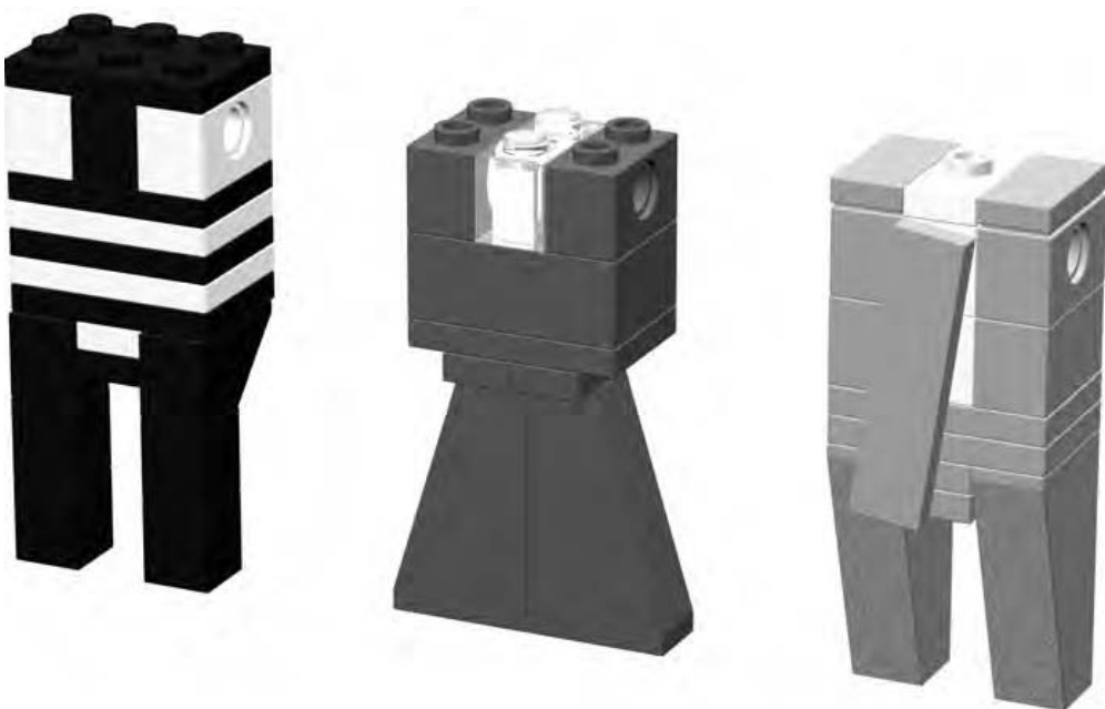
Figure 4-8: Clothes do make the miniland person. Remember that little details and careful color choices can add a great deal of realism and charm.
How do you know that the outfit on the left in Figure 4-8 is that of a referee? The striped appearance of the shirt and black pants are pretty good clues. You might finish this particular character off by adding a cap, such as the one you saw in Figure 4-7 and perhaps something to represent a whistle or flag that the character might be holding.
The dress in the middle of Figure 4-8 shows how you can use things like the 75-degree slopes to create a very feminine look. These slopes are centered under two offset plates, which help give this character a more slender waist. In addition, the at the very top center can be matched to the figure’s facial color, thereby giving the illusion that the dress has an open neckline.
Lastly, on the very right of Figure 4-8, you see the clothes of a hurried businessman. Don’t be afraid to use little tricks like attaching his tie off center in order to let the white of his shirt show a bit and to give the impression that he has just rushed off a busy subway car. It’s these little details that add character to your characters.
Lots of Legs
Heads and clothing are important, but then so are the legs and feet upon which your characters stand. Figure 4-9 shows some simple and subtle variations on the basic leg/shoe design you first saw in the standard figure earlier in this chapter (see Figure 4-3).
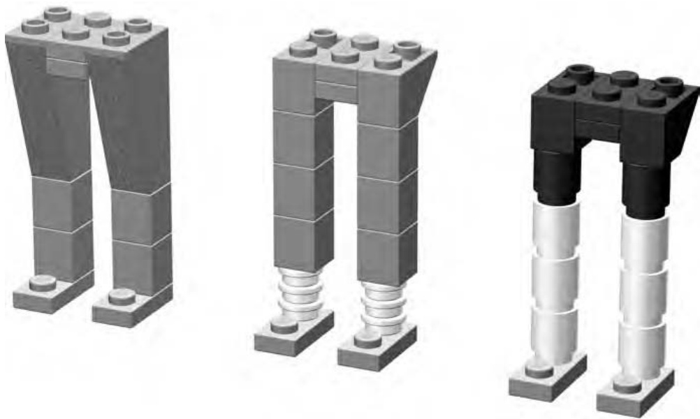
Figure 4-9: Most leg designs eventually create the two stud by three stud base upon which you then build the torso.
You can use the design on the left of Figure 4-9 for just about any character who is wearing long pants. To add a little fun to a figure, put him (or her) in pants that are too short (such as those in the middle image of Figure 4-9). Maybe your person is a nerdy scientist who has trouble picking properly fitting clothes. The more shapely arrangement of elements on the right of Figure 4-9 might suggest the legs and cycling shorts of an athletic character who just got off a mountain bike. Here again, match the lower cylinder bricks with the flesh color you chose for the face and arms.
Arms and Accessories
Part of what makes miniland figures so interesting is that the pieces you use to create certain parts of them will vary from character to character. For example, in the basic figure in Figure 4-3, you saw that a simple hinge plate was enough to suggest the presence of arms. But they didn’t portray any particular action or suggest any occupation that this figure might have.
Simple part substitutions and setting the arms at different angles can indicate a wide variety of actions or gestures. Figure 4-10 illustrates some ideas on how to add some life to your characters by simply adding flair to their arms and hands.
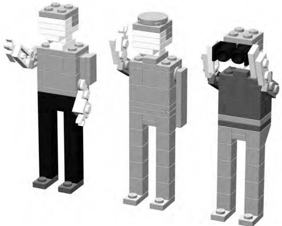
Figure 4-10: Hailing a taxi, saluting an officer, or watching birds—miniland folk can do just about anything you can dream up for them.
One interesting thing to note in Figure 4-10 is that the two leftmost characters both have hands made from plates with clips on the side. The character to the right, however, has no hands at all. Rather, I’ve used offset plates to extend the arms so they hold the binoculars. This helps illustrate the idea that it’s more important to achieve the look and feel of the thing you are trying to create as opposed to fretting over how to model every last detail. The basic miniland character, as shown in Figure 4-3, has no hands either. But it looks like a person nonetheless. Keep that goal in mind as you build.
On The Run: Making Miniland Figures Come to Life
Now you know how to model miniland figures and even how to dress them in various outfits. The next step is to give them the feeling of motion or action. They can’t all just stand there at attention with their legs perfectly straight. But unlike minifigs, miniland figures have no hinges on their legs. Thus, making it appear as if they are moving or doing something is a matter of selecting elements that once again give the appearance of something that isn’t really there.
As you can see in following examples, the action being undertaken is implied by the position in which you, the builder, pose the figure.
The character shown in Figure 4-11 appears to be in motion rather than just standing still.
With her arms swinging out from her body, the woman in Figure 4-11 looks like she may be walking. Notice the 75-degree outside corner slopes that I used to create the illusion that her long dress is moving with her legs. Rearranging the elements you used to create the legs and/or substituting other pieces is all that it takes to add some life to an otherwise motionless figure.
Now take a look at the person in Figure 4-12.
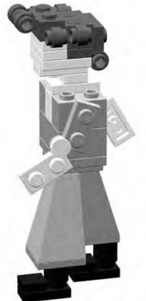
Figure 4-11: You can make a character appear to be walking by simply moving the arms and legs slightly ahead and behind the body, as shown in this illustration.
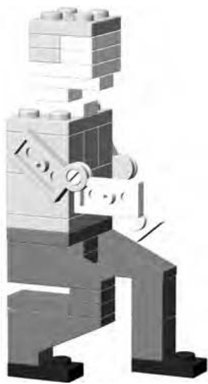
Figure 4-12: A few subtle changes (different pieces or just pieces in different positions) can give the impression of lots of action.
This fellow is crouched down, perhaps calling to a pet dog or watching as his bowling ball rolls down the lane. What you may notice is that he’s really not all that different from the very first character you saw back in Figure 4-3. In fact, to make him bend down, you only have to change or move a few pieces. In Figure 4-13, I colored those pieces in black so you can see which ones are different than those in Figure 4-3.
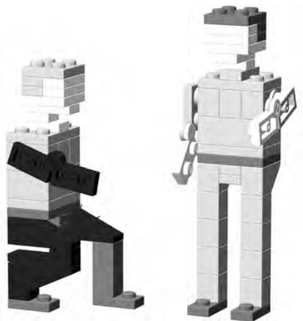
Figure 4-13: Pieces shown in black (as part of the figure on the left) are the only ones different than the pieces I used to build the figure on the right. Changing just a few elements changes the entire impression of what this character may be doing.
Miniland Buildings
Perhaps the only drawback to miniland-style creations is that buildings for these characters need to be quite a bit larger than those you might make for minifigs. Such models can be taxing on even some larger collections of bricks. That doesn’t mean that you shouldn’t try to make them, just that you might have to look at smaller structures for inspiration. In other words, a minilandscale Empire State Building is probably much too ambitious for most builders to undertake.
Creating a Scene: Combining Figures and Buildings
Working at miniland scale is a good way to practice creating facades of small buildings rather than the entire structure. A facade is the detailed front face of a building that might have plain sides or sometimes no walls or back at all. Movie studios have used facades for many years to re-create things like suburban street scenes or the main street of an old-west town.
You can create a small scene by combining your miniland figures and the facade of a building or two. These works are sometimes called vignettes or dioramas. The focus is on just what can be seen from the front; the side and/or back of the buildings are not intended to be part of the snapshot. Think of these scenes as three-dimensional photographs that capture a moment in time.
Facades work well in miniland scale for two reasons. First, they allow you to explore greater detail than you would capture if you were creating a similar minifig scale building. Second, they allow you to create a taller and wider model without having to worry about the sides, back, or even the roof of the building; thus they require fewer elements than a complete structure. To illustrate this technique, I’ll focus on a single vignette, exploring the components that you need use to help bring it to life.
Street Life: A Simple Downtown Scene in Miniland Scale
Figure 4-14 shows you the scene we’ll be discussing. It’s a simple street setting in front of a small cafe or shop that is located on a busy downtown corner. Along with the customer using the bank machine on the right, you also see a person about to mail a letter. As noted earlier, the larger scale of miniland construction allows you to include more detail than you normally see in minifig scale.
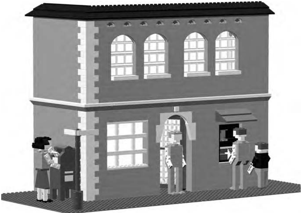
Figure 4-14: A typical downtown scene. Everyday objects and actions make scenes look realistic.
The People in Your Neighborhood
Let’s look more closely at the individual ingredients that make up this scene, starting with the characters that populate our street.
In the close-up shown in Figure 4-15, notice the child figure that is standing next to the adult using the automated banking machine. Creating smaller characters is really just a matter of reducing each of the main features (head, body, arms, and legs) proportionately. In the end, it’s really most important that the figure look right. If you build a child chracter and the legs look too long, then they probably are. Simply shorten them until things start to look the way you expect.
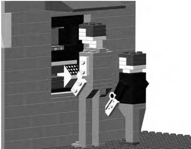
Figure 4-15: Characters doing realistic things will add a sense of life to your dioramas.
The bank machine itself is built into the exterior wall of the building. Although at first it may appear out of place in the context of the older-style building, it represents the type of modern changes that are sometimes applied to structures that are decades old.
The character shown in Figure 4-16 clearly has a letter in her hand that she is about to deposit in the mailbox. Notice as well that she’s wearing a variation on the dress that we first saw back in Figure 4-8.
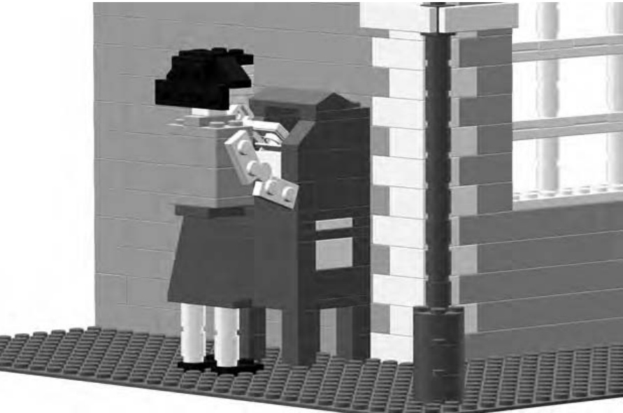
Figure 4-16: Mailing a letter is another everyday activity that you’d see on a real street.
Your characters may stand up best when you firmly anchor them to a baseplate, as shown in the Figures 4-15 and 4-16. You might find them a bit wobbly if you just place them on a tabletop or another flat surface.
Building the Buildings
Now let’s look at some close-ups of the architecture I used to construct the building itself. Figure 4-17 shows that the corner of the building was built as a quoin. This is a technique where you use bricks of different color, size, or texture to form a pattern much like the one you see in this illustration. It looks sort of like a zipper running up the corner of the building.
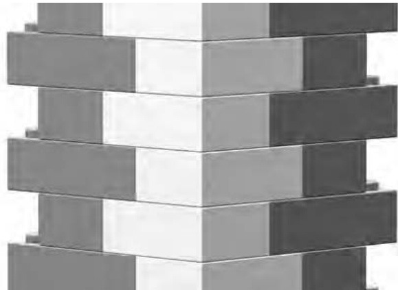
Figure 4-17: This architectural technique can be found on many real life buildings. Capturing such details in your LEGO creations gives them a more realistic feel.
In the example shown here, the quoin is mostly decorative. It is built from different colored bricks than the rest of the wall. Although it is an important part of the building—the corner—it is not structurally different than the two walls it connects.
Sometimes repetition of a single piece can add interest to an otherwise boring feature. The area above the large second-story windows could just as easily have been built with plain bricks. But as you can see in Figure 4-18, by using a number of arches side by side, I’ve created a more attractive visual pattern. Like the quoin, these arches are purely decorative.
The larger arches that are above the windows are a dramatic feature that adds flair to the model. To say they are above the windows is actually not quite correct. As you can see, they are positioned just in front of the many windows, but they also hide a portion of them. This is very common in buildings of this design.
Perhaps the most important thing you can try to do when you are assembling a vignette like the one shown in Figure 4-14 is to copy whatever details you can from real life buildings. Also, remember that building evolve over time as they are renovated or restored. Don’t be afraid to incorporate modern items in a building that looks like it was built in the last century.
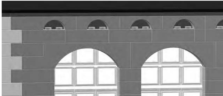
Figure 4-18: The arches above the large windows could easily be created with inverse slopes if you don’t have the actual arch pieces you need. See Chapter 3, Figure 3-25.
Behind the Scenes
Remember earlier when I talked about facades being used by moviemakers to create the illusion of buildings? Figure 4-19 shows our street scene example as it would appear from behind.

Figure 4-19: A behind-the-scenes peek at the diorama
Despite appearances, the building is essentially just two walls and a support column. You can clearly see there is no roof and no second floor, and the walls are far from complete. This is the point I made earlier—a facade allows you to concentrate on just how things look from the front and not worry about interior details or even walls.
Figure 4-19 also shows the support column from a better angle since you are now viewing the facade from the back. I’m using the column to support the end of the wall that contains the bank machine (see Figure 4-14 for a front view). A sturdy column, linked to the end of the wall, makes an excellent substitute for the side walls you don build for a model like this. (Refer to Figures 2-24 through 2-27 in Chapter 2 for pictures of different types of columns.)
In the close-up in Figure 4-20, you can see that the column is tied to the wall with a simple beam. This is another way of saying it’s built into the wall. Connecting (or tying) the two is really just a matter of using a or brick or even a composite beam like the one you saw in Figure 2-21 in Chapter 2. The beam is built into the column and extended out until it also becomes part of the wall. The second illustration in Figure 4-20 shows both the wall and the column with a few bricks removed from each. This better illustrates how the brick joins the two structures together.
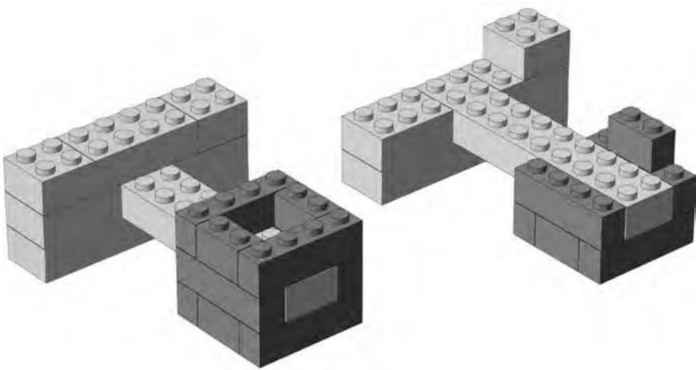
Figure 4-20: A close-up of the column and part of the main wall on the left. The image on the right shows the same two structures with bricks removed to reveal how the connects them.
Using a single column, instead of an entire wall, can help you to save bricks. For instance, if you are short on the color of bricks being used for the front of the building, you can use a different color to build the column. If you place the column behind a solid part of the facade, rather than sitting it behind a window, it is reasonably well hidden. Therefore the bricks you use to build the column can be any color or combination of colors you have at hand.
Review: Miniland Scale, Big Possibilities
You’ve seen how very unique miniland scale figures can be created from mostly basic bricks, plates, and slopes. The other technique you looked at— creating a vignette of a scene—gives you a little world in which to put your new figures. As a follow-up project, you might want to try creating a larger street scene with more building facades and a larger cast of characters going about their business. Or, you may wish to try working on a miniland-scale car or even a boat for your figures to travel in.

J U M B O E L E M E N T S : B U I L D I N G B I G G E R B R I C K S
In Chapter 3, I talked at length about scale and how it relates to building LEGO models. The discussion lead you through the steps to create a small-scale train station to add to a small-scale LEGO town. In this chapter, you’re going to go the other way. You’re going to build a model that is larger, not smaller, than the real life object it represents.
One great way to demonstrate this idea is by taking advantage of an interesting characteristic of LEGO bricks; you can use them to make other LEGO bricks. No, I’m not suggesting that you melt down your bricks and remold them. Rather, I’m talking about the technique whereby you use individual bricks to construct a jumbo brick that looks exactly like the small version, just many times larger.
When you go to build a jumbo brick, you use a technique called scaling up. This is the idea that you take the dimensions of the real life object and multiply them by some number. That number is the scale factor that you first saw in Chapter 3.
In your first encounter with scale, I suggested that a minifig world might be built to a scale of around 1:48. In other words, a model building or vehicle would be 48 times smaller than the same object in the real world. In this chapter, you’ll explore macro building, or making the model larger than the real life object.
Macro building involves reversing the relationship of the numbers in your scale. For example, the model in Figure 5-1 is ten times bigger than the real brick it represents. That means it was built to a scale of 10:1.
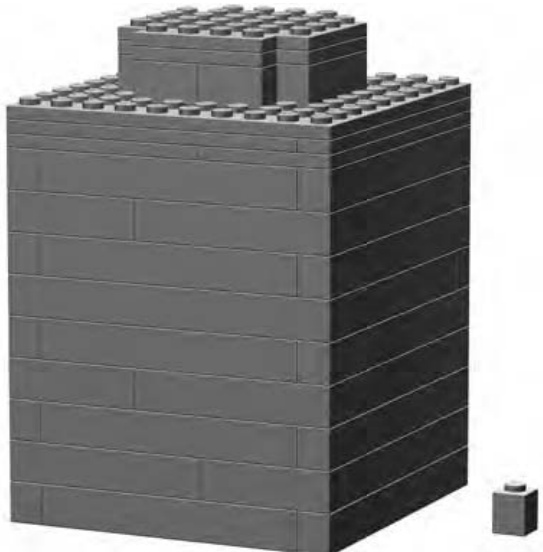
Figure 5-1: This jumbo model of a brick dwarfs the real that served as inspiration. It is ten times larger and stands nearly inches tall.
NOTE Remember from Chapter 3 that the number on the left signifies the number of real objects you are talking about and the number on the right represents the model version.
For the example shown in Figure 5-1, you would say that you are building a brick to ten times scale —also sometimes written as 10X.
It’s important to note that the ten times scale is applied to each of the three dimensions. Take the length and multiply it by ten, then multiply the width by ten, and finally do the same to the height. This gives you the final size you are aiming to build. So in the example in Figure 5-1, your brick has sides that are 10 studs wide, by 10 studs deep, by 10 bricks or courses high.
NOTE You can also describe this process as building to a “factor of” something. Keeping with the current example, you can say that you are building jumbo bricks to a factor of 10. This is an expression you may hear from time to time, and it’s an effective way of describing the scale to which you are building something.
Figure 5-2 shows a brick scaled up to a factor of 4. This might make it a little easier to see the relationship between the two numbers that make up the scale.
At first glance, you might think that Figure 5-2 is a visual representation of 1:4 scale. In fact, it is just the opposite. It shows 4:1 scale. You can see that it would take four of the actual brick (shown on the left) to equal the height of the macro model (shown on the right). Don’t forget that the length and width are also four times larger in the jumbo version.
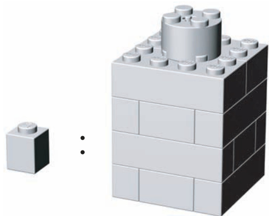
Figure 5-2: 4:1 scale demonstrated
NOTE As I discuss the scale of models and objects, I am talking about only one dimension at a time. For instance, I say that the jumbo is four times as high or four times as wide as the real thing. If I was to talk about all three dimensions (length, width, and height) at the same time, I’d be discussing the volume of the object. That would tell you how many of the real objects it would take to occupy the same amount of space as the jumbo. For example, for a 4X model, you would multiply Put another way, a 4X scale brick takes up as much space as 64 normal sized
There isn’t much to building a 4X jumbo like the one in Figures 5-3 through 5-5. In fact, it’s as easy as one, two, three.
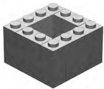
Figure 5-3: Step 1
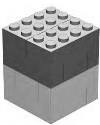
Figure 5-4: Step 2
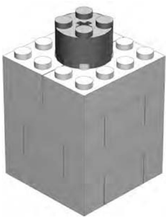
Figure 5-5: Step 3
In step 1, I actually show you two courses of bricks because this construction technique should be familiar to you by now. You’ll recognize the arrangements of and bricks as the chimney pattern from Chapter 2.
Step 2 isn’t much more complicated. You add a third layer of ’s and ’s and then cap the model off with two bricks. To appreciate the true effect of macro-sized bricks, always construct them using the same color elements.
In step 3, a cylinder brick finishes our jumbo-sized model. Although it’s possible to cover the studs using tiles, I’ve avoided this technique for two reasons. First, it adds to the number of pieces you need to make each brick. Second, if you leave exposed studs on the top of each jumbo brick, you can later build with them very much like you use the real versions at normal size. I’ll discuss this later in this chapter.
Scaling Up: How It’s Done
Now you’re ready to build your own jumbo brick. To begin, take a differentsized brick and build it to 4X scale. The classic brick should provide a good example of how the same scale can be applied to different sized models.
When you’re scaling up a simple object like a LEGO brick, it’s really just a matter of multiplying each of the original dimensions by the factor you’re using—in this case, 4. In Table 5-1, I show you the actual dimensions of a brick and the dimensions of the jumbo version at 4X scale.
Table 5-1: Dimensions for Building a Brick to 4X Scale Size
| Real Brick | Jumbo Brick Model | |
| Width | 2 studs | 8 studs |
| Length | 4 studs | 16 studs |
| Height | 1 brick | 4 bricks |
The calculations here are really fairly simple. You know that your actual model will be 8 studs wide, 16 studs long, and 4 bricks high. Begin building this example by laying down a foundation layer that is studs. (The example shown here, beginning with Figure 5-6, uses and bricks, but you can use whatever pieces you have available as long as the end result is the same.)
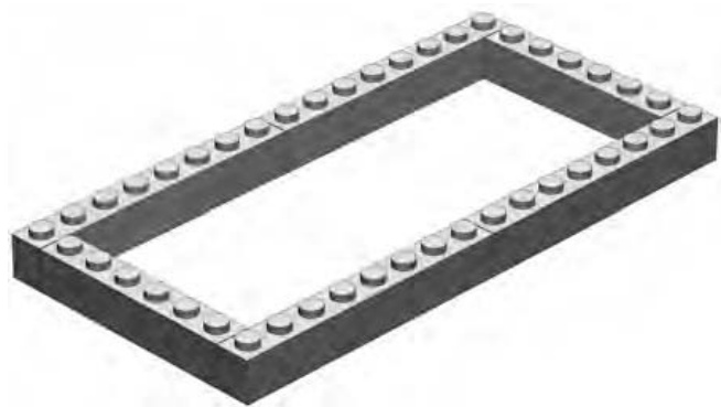
Figure 5-6: Step 1
Next, as shown in Figure 5-7, you need to build another course on top of the initial one you set down. (Don’t forget to always overlap as much as possible.) The third layer, shown in Figure 5-8, is just more of the same.
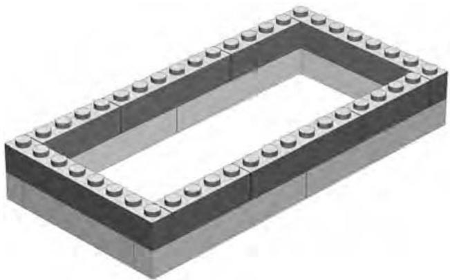
Figure 5-7: Step 2
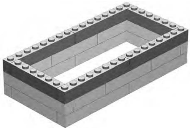
Figure 5-8: Step 3
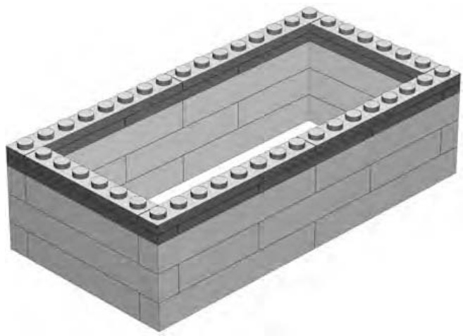
Figure 5-9: Step 4
For the fourth and final layer, begin to finish the jumbo by covering the top completely, not just with another outside course of bricks. You can do this in one of two ways: either by using two layers of plates around the top of the model (as shown in Figure 5-9), and then topping things off with some and plates (as shown in Figure 5-10); or by building the final course using just bricks and no plates at all.
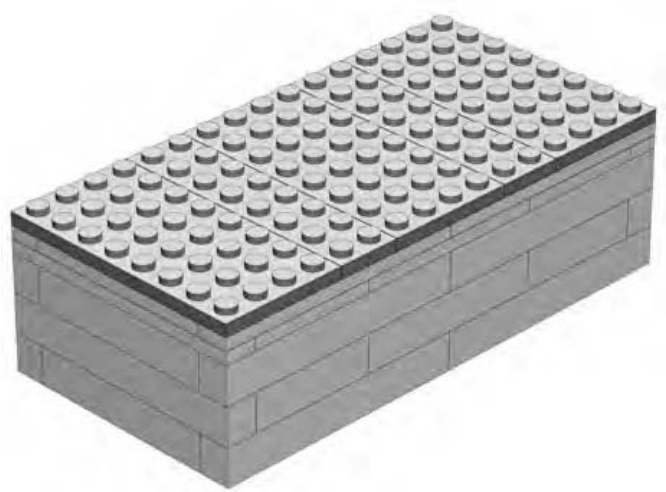
Figure 5-10: Step 5. In place of plates as the top layer(s) you can use bricks if you have them.
NOTE For simplicity’s sake, I’ve not included the tubes (inside the brick) with these instructions. However, a simple solution to creating them will be shown later in this chapter when you build a jumbo version of a 45-degree slope.
Finally, you need some studs on top of this jumbo. But where do they go? The you looked at earlier was easy since the stud went right in the middle.
For this example, you need to add the eight studs found on the top of every standard brick. Look carefully at an actual brick. You’ll see that the studs are evenly spaced and that they are closer to the edge of the brick than to each other. In fact, in Figure 5-11, you can see that A is only about half the width of the distance indicated by B.
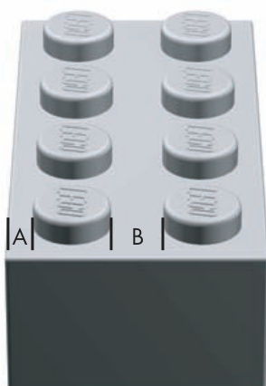
Figure 5-11: By studying actual elements, you learn facts that will help you make your jumbo models look more realistic.
When you look at the top of the finished jumbo brick in Figure 5-12, you will see that the cylinder bricks, used to represent studs, should be placed one stud away from the edge of the brick. At 4X scale, they will also always be two studs away from the next nearest cylinder.
In other words, the cylinders are placed twice as far from each other as from the edge of the brick, just as you saw in Figure 5-11.
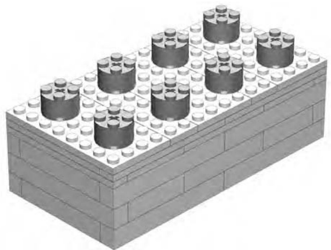
Figure 5-12: Step 6. The finished model of a 4X jumbo brick.
If you look carefully at Figure 5-12, you will see that the studs feel right. Although the calculations for their placement may not be precise enough to land a man on the moon, they are more than sufficient to build jumbo bricks.
The Walls Are Closing In!
Because you only scaled up the brick by a factor of 4 in the preceding example, you again used bricks to represent the side walls of the brick. The reason for this is that even though the scaled-up brick is bigger than the previous example (see Figure 5-5), the thickness of the walls is the same on both bricks. Scaling them up by the same factor means the jumbo models should have walls that are equally thick.
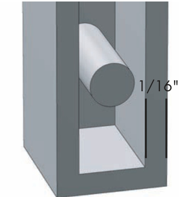
Figure 5-13: Standard LEGO bricks have walls that are approximately of an inch thick.
The thickness of the outer wall of a real brick (or a brick) is just about of an inch. The width of the brick itself, as seen in Figure 5-13, is just over of an inch.
If we take of an inch and multiply it by a factor of 4, you get or inch—almost the same as the actual brick.
This means that a real brick is just about the right width to duplicate the outer wall of a jumbo brick built to 4X scale.
For the 10X example shown in Figure 5-1, you need to use bricks to simulate the thickness of the brick walls. For the 4X version, those would probably have looked unnecessarily chunky and out of proportion. You can see what I mean in Figure 5-14. Here, you use bricks used for the jumbo on the left, which allows it to have walls that are the correct proportion. The example on the far right uses bricks and, as you can see, the walls are much too thick. In fact, there’s no opening for a stud, so this is obviously a bad choice.
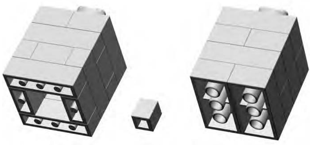
Figure 5-14: One of these things is not like the others, and it might not be the one you think! The version on the right was built with the wrong bricks and lacks the open core of the jumbo version (far left) and the real (center).
The decision about what size bricks to use to construct any model is most often made on a case-by-case basis, so it’s nearly impossible to devise or apply a single rule that applies to every situation. Given enough other knowledge, however, it is reasonable to assume that you can work out many of these small details as they present themselves.
Sometimes you need a test build to see if a particular solution holds water. In the instance just described, it would be sensible to set out the first layer of bricks in both sizes ( and ) and compare them. Right away you would see that with bricks, the resulting scaled brick would have a hollow underside that would be too small (or even nonexistent) in relation to its overall size. Conversely, you would see that if you made the model of bricks, it would look more like your original.
NOTE test build is like sticking your foot in a pool to find out the temperature of the water. Instead of jumping in completely, you just go partway in to see if things are what you expect—that the water isn’t freezing cold. When you are building with LEGO bricks, you can do something similar. Build a section of a large model to see if a certain technique is working. Or try building a small-scale version of something to see if it translates well into LEGO bricks. If it does, then build a larger version.
By tinkering and experimenting during a test build, you can save yourself a great deal of frustration later on. Although it may be easy to spot the correct approach in the example of the built to 4X scale, imagine instead that you were trying to build a 10X scale brick. Take it one step further and imagine you made the wrong choice and tried to build the side walls from bricks instead of bricks. You could easily have put together two or three hundred bricks before you realized the mistake in your selection of materials. However, if you had done a test build of even a layer or two and then evaluated the results, you would likely have corrected yourself early on. In fact, it may not have even been necessary to build an entire course of the jumbo brick. You would likely have spotted the problem by just building a few layers of one or two corners.
Other Parts, Same Technique
You might be wondering, “Are there other parts, besides standard bricks, that make good jumbos?” The answer is “yes.” You can scale up many other elements from within the LEGO system just like the basic bricks I’ve already shown you. Standard slopes and plates are relatively easy since their geometry is simple to copy. Other elements, such as arches, Technic pieces, or some of the specialized elements are also possible to scale though they might require a bit more planning and attention to detail.
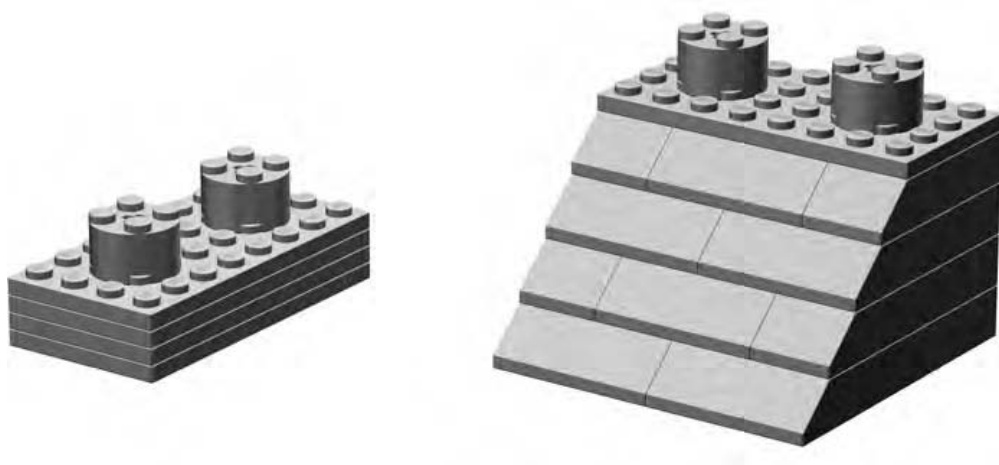
Figure 5-15 shows a couple of example pieces to get you started.
Figure 5-15: A plate and a 45-degree slope
Both of the elements shown in Figure 5-15 make excellent subjects for macroscale building. Here’s how to make your own versions of these common pieces.
Plate—Instructions for the Jumbo Version
If you’re looking for a small but interesting element to get started with jumbo building, I strongly suggest a plate. Once you’ve finished the larger-scale version, try holding it in one hand while you hold a real plate in the other. The sense of scale should become quickly obvious when you realize that a tiny piece that you normally pinch between two fingers becomes big enough to nearly cover your palm!
As shown in Figures 5-16 through 5-19, constructing this element in 4X scale is pretty simple.
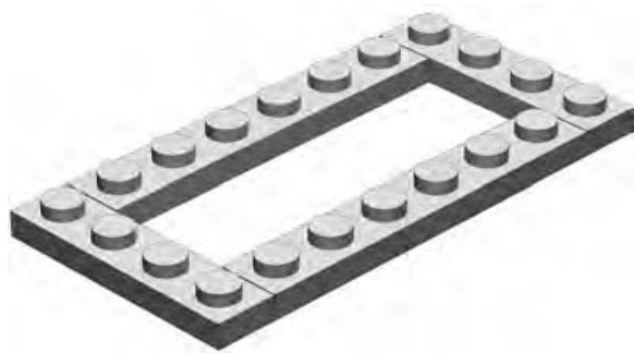
Figure 5-16: Step 1
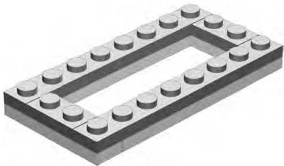
Figure 5-17: Step 2
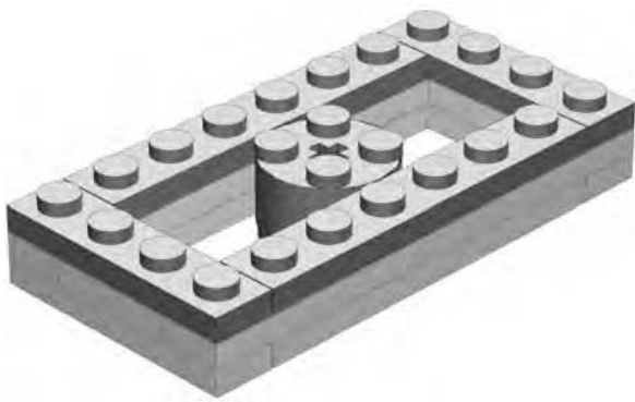
Figure 5-18: Step 3
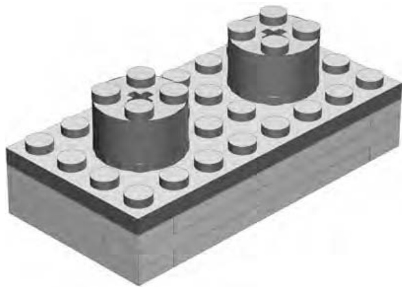
Figure 5-19: Step 4
The studs on the final model (Figure 5-19) appear a bit large, but they are built from a fairly common piece (the cylinder brick). If you have cylindrical plates, you can substitute two for each of the cylinders I used here to make the size appear more accurate.
45-Degree Slope—Instructions for Jumbo Version
The 45-degree slope is another common element that’s fun to re-create as a jumbo model. When you’re choosing which elements to scale up, keep in mind that you may need large quantities of certain pieces. For example, the 45-degree slope uses a number of actual 45-degree slopes to re-create the angled side of the jumbo brick. Figures 5-20 through 5-24 show the steps you need to follow to build this element. As you can see, the model requires four slopes and six slopes. Building the same element to a larger scale (10X or 12X) requires even more actual 45-degree elements. Deciding which pieces to re-create as jumbo versions will, therefore, depend largely on whether or not you have enough of the actual-sized elements in your collection.
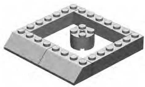
Figure 5-20: Step 1
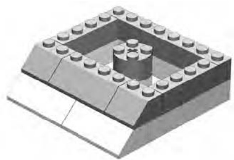
Figure 5-21: Step 2
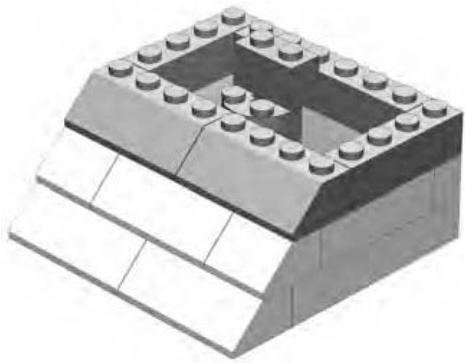
Figure 5-22: Step 3
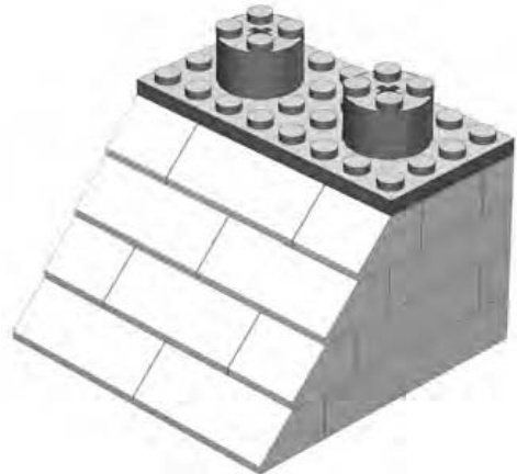
Figure 5-24: Step 5
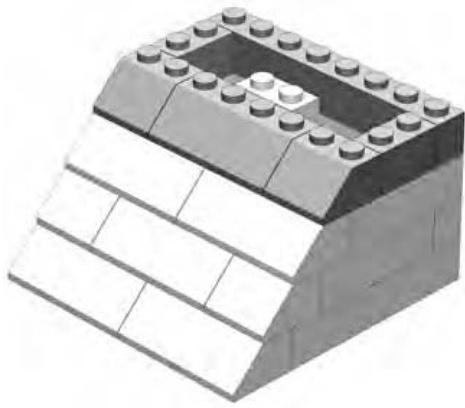
Figure 5-23: Step 4
Building with Jumbo Bricks
You’ll find that the plate and the slope shown in the preceding pages can connect to each other in almost the same way at their regularly sized versions. The only real difference is the way in which they grip in order to stick together. Normal-sized bricks use the friction between the studs on top and the tubes inside other pieces to lock together, but jumbo elements lock together differently.
Remember when I mentioned earlier that you were leaving the smallsized studs exposed on the top of each of your jumbo elements? That was because the studs you built (the scaled-up versions) don’t work to hold jumbo bricks together. Instead, you must rely on the normal-sized exposed studs to connect to the pieces of another jumbo brick. This means it’s possible to build an entire LEGO set out of jumbo bricks.
This isn’t unlike the idea of submodels that I talked about in Chapter 3. In the case of building an entire LEGO model out of jumbo elements, you could consider each of the jumbos to be a submodel. The main structure then is the model that you build from them. The building process is twofold. First, you need to re-create each individual piece in a jumbo size. Then you need to assemble the set exactly as you would the normal-sized version. In Figure 5-25, you can see that I’ve finished the first step, building jumbo versions of a number of different elements.
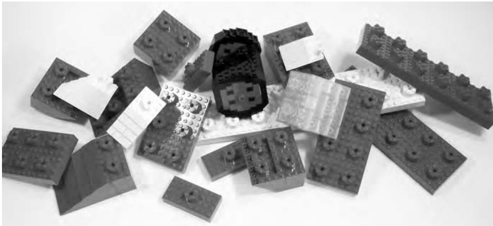
Figure 5-25: Once you’ve built each piece at 4X scale, you’ll have a jumbo pile of bricks ready for the next step.
The jumbo elements in Figure 5-25 don’t look like much. In fact, they just look like a pile of assorted LEGO pieces, though each of them is really a 4X jumbo model.
When you put them all together, just as you would normal-sized pieces, you end up building a complete LEGO model to jumbo scale. In Figure 5-26, you see the 4X model that arises from the pile of assorted jumbos shown in Figure 5-25. As well, in Figure 5-26 you see the original, much smaller, airplane model that I used as inspiration.
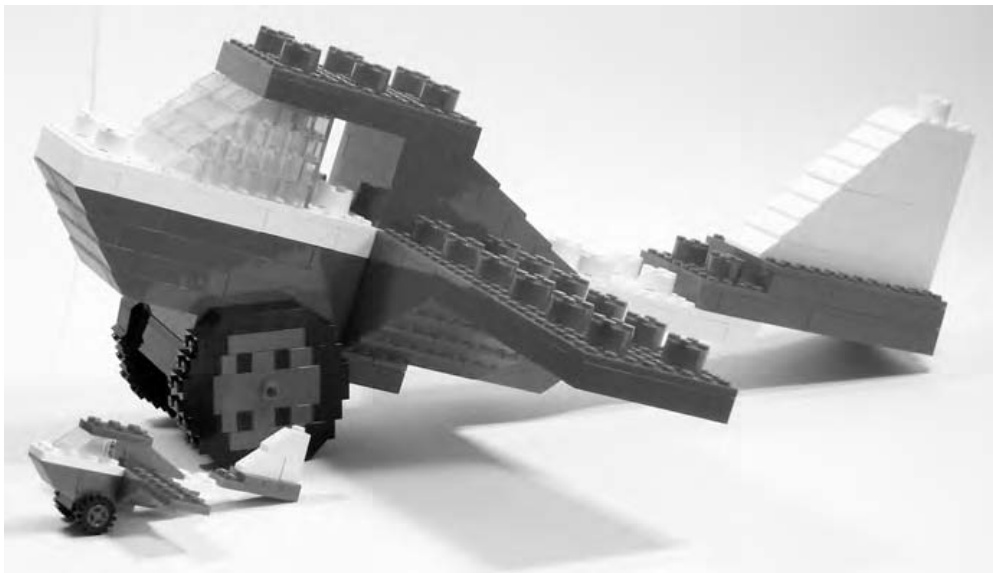
Figure 5-26: The inspiration for this jumbo plane is small enough to fit under its wing.
Bear in mind that this type of model—an entire set build of jumbo elements—can consume large quantities of bricks, so you might want to select to build a small set initially. In addition, you’ll want to work at a reasonable scale, such as the 4X technique you used for the last few examples.
Best Solutions from the Simplest Plans
As you work through virtually any LEGO project, you will find yourself questioning the usefulness of this part or that part in this situation or that. You’ll wrestle with choices between various techniques and, of course, at what scale to build something. It’s all part of the art of LEGO building and part of the challenge that puts this building system at the top of its class. To that end, there is one principle that will help you no matter what you are constructing:
Make things only as complicated as they need be but no more.
Using the cylinder brick to represent the stud on a 4X model (Figure 5-5) is an example of this kind of solution. It uses the minimum number of pieces required to complete the task and no more. When you’re building or designing a new model, try always to focus on simple solutions like that.
Other Scales: What Scales Work, and Why
In theory, you can build a jumbo brick to just about any scale you like.
In practice, some scales work better than others.
The smallest scale that works well is 4X. That’s one reason I’ve used it several times throughout this chapter. In fact, most even-numbered scales work well, because it’s much easier to center the studs on the tops of these elements. It’s more complicated to put studs on top of a brick that has odd lengths for sides.
You should also keep two other issues to keep in mind when you’re deciding what scale to build your jumbos. First, you’ll probably want to build some plates, not just standard height bricks. Scales such as 4X, 6X, 10X, and 12X all offer easy solutions for making jumbo plates. For example, at 10X, the jumbo model of a standard brick is ten real bricks high. Therefore, a 10X scale plate is three real bricks and one real plate high.
NOTE A jumbo plate, regardless of which scale you choose, will always be one-third the height of a jumbo brick at the same scale.
Similarly, at 12X, the jumbo model of a standard brick is twelve real bricks high, and a 12X scale plate is four real bricks high. You can see examples of the four scales I just mentioned, along with a standard brick, in Figure 5-27.
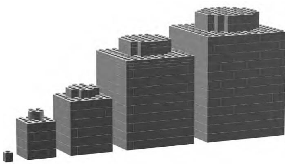
Figure 5-27: From left to right: a standard brick, and the 4X, 6X, 10X, and 12X jumbo versions
The other tricky thing is dealing with the jumbo-sized studs that you’ll need to finish off your jumbo size elements. You’ve already seen that at 4X scale, you can easily use cylinder bricks as studs. However, at 6X scale, the cylinder brick is the right shape but not quite tall enough. For 10X and 12X scales you will almost certainly find yourself creating studs out of square bricks rather than cylindrical ones. Later in this chapter, I’ll discuss how best to handle studs scaled up to jumbo size.
Picking the Right Scale
For the first example in this chapter (Figure 5-1), you saw a 10X scale of a brick. Then you learned how to scale some other pieces up by a factor of 4. Both of these scales worked just fine. In other words, the jumbo bricks you made looked just like the original regular-sized bricks, only bigger. Look carefully though at the detail needed to fashion the hole in the middle of the 10X Technic brick shown in Figure 5-28.
Would it be possible to have achieved this level of detail (Figure 5-28) if you tried it in 4X scale? No, probably not. The hole through the brick is a complex shape that benefits from being built to a larger scale where you can better define the curves.
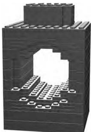
Figure 5-28: A Technic brick offers an interesting challenge when you are building a jumbo version. Creating the hole in the middle is best achieved using larger scales.
Examine the way in which you were able to create a fairly realistic-looking stud on top of your 4X brick in Figure 5-5. Would that same technique have worked for a 10X brick? No, not at all. The cylinder brick simply wouldn’t be big enough to represent a stud at 10X scale. Instead, you need to build the stud out of several smaller elements to make it appear correctly sized.
NOTE You can find complete instructions for building the 10X Technic brick shown in Figure 5-28 at www.apotome.com/instructions.html.
It’s easy to see that just as it is important to use the right parts for the right job, you must also choose the right scale at which to build. This idea applies to just about any LEGO model you may try to build. Trying to build a 6-inch-long Titanic might result in a ship so small it is hard to determine what inspired it. Starting with such a large inspiration can be hard, unless you are willing to work toward an equally large model. Looking at it another way, it is probably easier to build a 6-inch-long fire engine and have it contain a few essential details that help capture the feeling of the original than it is to do this for the Titanic. Think about matching your building scale with the item you are trying to build.
Approximation
Building a model out of LEGO bricks requires you to make many decisions. You need to figure out how large a model to build, what color bricks to use and, very often, how to handle the tiny details that may not be possible to replicate exactly. To make your model look as realistic as possible, you will find that you need to approximate certain features to at least give you the look of the original. Sometimes just coming close is close enough. Where else in life do you get a great deal like that?
Jumbo bricks are no exception. Almost all have a tiny feature that can be hard to replicate. I’m talking about the studs on each element.
Let me use a 10X-scale stud to easily demonstrate this problem. First, refer to Appendix B of this book. There you will find information about printing out one of the model design grids you will use throughout this book. Print out a copy of Design Grid #1. It looks very similar to traditional graph paper. On that paper, draw a circle with the correct diameter to represent the stud. Imagine you’re looking down at the top of a 10X jumbo brick, like the one shown in Figure 5-1.
Now start shading in squares until you almost fill the circle without really going outside of it. You should find that your drawing looks like Figure 5-29; the shaded squares don’t quite fill the circle. This means that this example of a jumbo stud will be just a bit smaller than if you could make it perfectly cylindrical.
Now shade in additional squares until your drawing looks like Figure 5-30. This version of the stud is slightly larger than if you could model it to be exactly cylindrical. Neither technique produces a perfect jumbo copy of the original. These are both examples of a shape being approximated with LEGO bricks.
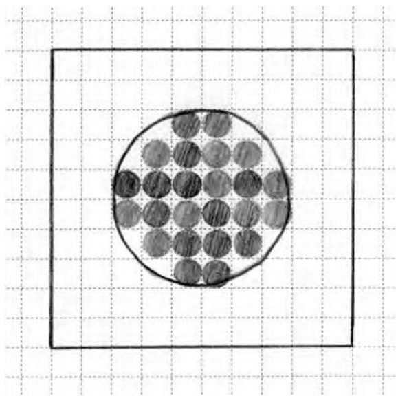
Figure 5-29: The small shaded circles within the larger circle represent the tops of actual bricks that will be used to re-create the jumbo stud.
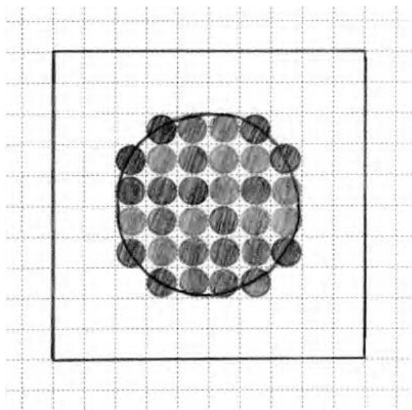
Figure 5-30: In the second example, shown here, more real bricks are added. This makes the jumbo stud appear larger than in Figure . You can use either version depending on your preference.
Figures 5-31 and 5-32 show how the two different studs appear when built of actual bricks.
Both techniques work, and two 10X macro bricks will connect together with either size, so it’s a matter of which one you like best. Approximation is as much about what you feel looks best for your particular model than it is about what is correct from the most technical point of view.
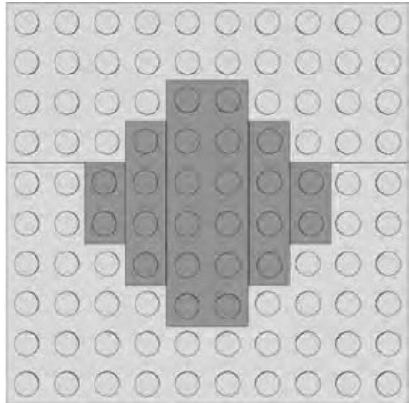
Figure 5-31: The stud in this example is a bit smaller than the relative diameter of a real one, but it will work just fine.
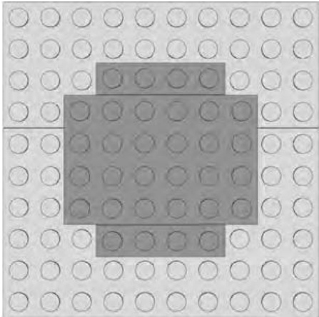
Figure 5-32: The stud in this example is slightly larger than the correct diameter, but it will also suffice as a jumbo stud.
Review: Jumbo Bricks Are Just the Start
So you’ve built a few jumbo bricks and you understand the concept of macro building. Now you’re looking for other projects to build using the same technique. There is really only one rule that applies when you choose subject matter for macro models:
Start small and don’t build too big.
First, try re-creating other elements you have in your collection. You may want to tackle a headlight brick or maybe see if you can find a way to build the texture on the face of a grille brick. (See Appendix A for illustrations of these and many other pieces.) Pick pieces that you already find interesting and know you’ll enjoy seeing in large scale. And remember, try smaller elements first. For instance, don’t try building a Technic brick right off the bat. Try a first to see if you can figure out the geometry you need to make the hole appear round.
Then, why not try building an entire set out of jumbo bricks, as you saw in Figure 5-25? Again, select a set that is already very small. Start with a set that has perhaps 10 or 12 pieces at most. Then, as you get more comfortable with the technique, you might want to try something bigger. Remember, the larger the set you are trying to build from jumbo elements, the smaller scale you will want to use. In other words, you might be able to build a 10-piece set at 10X scale, but if you were building a 25- or 30-piece set, you might want to stick to 4X scale.
Regardless of the scale or subject matter you choose, I think you’ll find that jumbo bricks are fun to build and will catch the eye of anyone who happens to see them.
M I C R O S C A L E B U I L D I N G : M O R E T H A N M E E T S T H E E Y E
In the last chapter, I showed you several macroscale building techniques; there you learned to make models much larger than the objects they represent. This chapter focuses on the opposite technique, something called microscale building. As the word micro indicates, this scale is very small. Keep reading to find out just how small. If you are someone with a limited supply of LEGO bricks, or perhaps you do your building in a confined space, then the microscale route might work well for you. You can still create interesting models no matter how limited your palette of pieces might be.
Figure 6-1 shows an example of the type of subject matter you might explore when building at this scale.
Though only 7 inches long, this microscale cargo ship captures many of the details of the real thing, including shipping containers, the bridge, and the always necessary smokestack.
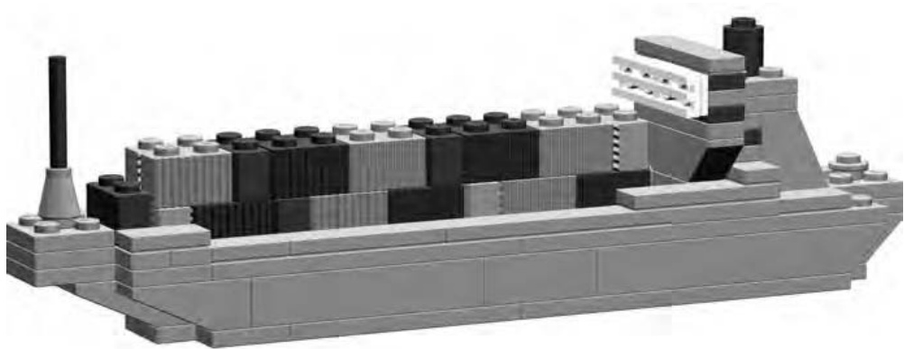
Figure 6-1: Microscale works well when the real life inspiration is huge.
Now that you know that micro is yet another scale at which you can build models, you probably want to know how to define micro. How small is small? Let’s back up a couple chapters and think about the train station (shown in Figure 3-4).
In Chapter 3, I showed you how to build the walls, doors, and windows of that building to accommodate the standard-sized LEGO minifigs. However, suppose you wanted to build the train station smaller, maybe only one-half or even one-third the size. In such a case, the features of the building would no longer be properly sized for minifigs. What label then would you apply to the scale of the building? In a word: micro. In this book, the term micro or microscale applies to models of objects that are built much smaller than is suitable for minifigs to live or travel in.
So far in this book, I’ve talked about several different scales to which you can build models. To put them all in perspective, take a look at Table 6-1, which describes each one.
Table 6-1: Comparison of Various Scales Used to Build LEGO Models, from Largest to Smallest
| Scale | Description |
| Macro | Discussed in Chapter 5.When you are working at this scale, the model ends up being many times larger than the original object. |
| Lifesize | As the name suggests, models you create at this scale will be exactly the same size as the original object. These could be sculptures (as seen in Chapter 7) or just about any faithful reproduction of a real life object. |
| Miniland | Models and figures built to miniland scale are roughly twice the size of minifig scale constructions. This is the scale used to create the miniland displays at the LEGO theme parks. |
| Minifig | The train station we built in Chapter 3 was created at minifig scale. Buildings, cars, and other objects are all built in proportion to the minifig characters. |
| Micro | I'll show you microscale in this chapter. The models built this way are typically even smaller than those built using the minifig scale. |
NOTE In order to standardize microscale building for the purposes of group displays, some LEGO builders have decided to use a cylinder brick to represent the size of a person within the microsized world. In other words, in such cases, one brick in model height is equal to roughly 6 feet in the real world. This should give you a good idea of the scale of the micro world.
Of course, there are any number of scales upon which you can base your models. For instance, you may decide to build a 1:3 replica of the grandfather clock that sits in your living room. That certainly wouldn’t be minifig scale. The model isn’t larger than the original, so you know it’s not macro. In fact, it really doesn’t match any of the major scales noted above. That’s okay. The scales I laid out in Table 6-1 are just guidelines, not rules.
These scales are, however, useful if you want to understand the scale at which you are making your models. For instance, suppose you are building a model that you want to display alongside one built by a friend or a member of the LEGO builders group to which you belong. If you both (or all) agree to build something to minifig scale, you each know what that means. The minifig label provides a reference to a particular size of building. That way you don’t arrive with a 1-foot-tall warehouse that’s supposed to go next to your friend’s 3-foot-tall ice cream stand. That could be embarrassing!
Microscale: Small Scale with Big Possibilities
When we looked at minifigs back in Chapter 3, I helped you figure out that structures or vehicles intended for those little folks should be built to about 1:48 scale. However, microscale models aren’t locked into one set of numbers, much like the macroscale bricks back in Chapter 5 that weren’t all built to the same scale. For example, a 1-foot-tall model of the Empire State Building in New York would be approximately 1:1250 scale, because the actual building is 1,250 feet tall. On the other hand, a 1-foot-tall model of the Great Pyramid in Egypt would be approximately 1:480, because the actual pyramid is about 480 feet tall.
This might seem a bit confusing because earlier I mentioned that some builders use a cylinder brick to represent the height of a microscale person. The examples of the Empire State Building and the Great Pyramid are obviously not built to the same 1-brick-equals-6-feet specification. In fact, they aren’t even built to the same scale as each other! But they are microscale examples nonetheless. These examples demonstrate that the actual scale can vary within the micro world, but models still hold to the same principle; they are extremely small versions of very large things. Just as you did in Chapter 5, where you learned to build 4X and 10X versions of the same brick, you can use different numbers to achieve the dimensions for a microscale model.
It’s also worth noting that neither of these two models would be classified as minifig scale since even minifigs would look like giants next to the LEGO version of either structure. Instead, both of these models are definitely considered microscale for the reasons I’ve already mentioned.
Getting Started: Ignore the Details
Okay, you don’t really want to throw out every detail, but many smaller features on large objects are just not going to be included in your final work. In Chapter 5, I talked about a technique called approximation. This is the building method where you try to give things the look and feel of their real life counterpart without necessarily duplicating every last detail.
That same principle can also be applied to microscale models. The easiest way to do this is simply to look at the thing you are modeling and try to see only the characteristics that stand out the most. How does that work? To find out, let’s go back to the Empire State Building as an example of how to create a model at this scale. If you tried to create a minifig-scale version of that building, it would still have to be more than 26 feet tall! Remember that in Chapter 3 you discovered that minifig scale is about 1:48. Because the real building is 1,250 feet tall, you would divide that number by 48 and end up with 26.04 feet as the height of your model.
Most people don’t have enough LEGO bricks to tackle a project of that size. A microscale version of such a large building makes much more sense. But in choosing microscale, you need to recognize that smaller details such as window sills, decorative statues, or signs may have to be left out so that you can capture the essence of the building in something less than 26 feet.
The Empire State Building has a unique shape that is easily recognized. Bringing it to life in microscale involves trying to re-create that shape with as few elements as possible. All you are trying to achieve is the feeling that your model is this building not that it is an exact replica.
Start by sketching the shape of the building on some graph paper.
NOTE For this next example, I’ve used one of the model Design Grids. This is special graph paper that has lines drawn to the same size and shape as real LEGO elements. Refer to Appendix B of this book for more information on the Design Grids. For now, just follow along with the example shown here.
I found some images of the actual building on the Internet and used them to come up with the drawing you see in Figure 6-2.
Notice that I’ve only drawn the outline of the building in this first illustration. The silhouette is the most important thing I want to achieve in making this model. As previously noted, I’ve essentially left out all the details at this point. Seeing only the shape of your subject helps you see the big picture of the model you are attempting to produce. Because microscale building is often about creating the illusion of a larger object, it’s very important that the model look right at first glance.
How did I know how big to draw it? I didn’t. I just guessed, though I obviously wanted to make it fit on a single page or less. You may find that your first few drawings are too large or too small or that they don’t capture the profile the way you want. Don’t give up. Making a second or third sketch doesn’t take that long, and your plan will likely improve each time. Note that at this point, I’m not even worrying about designing to a particular scale, I’m just focusing on finding a design that captures my subject.
Next, I begin to add the major details (see Figure 6-3).
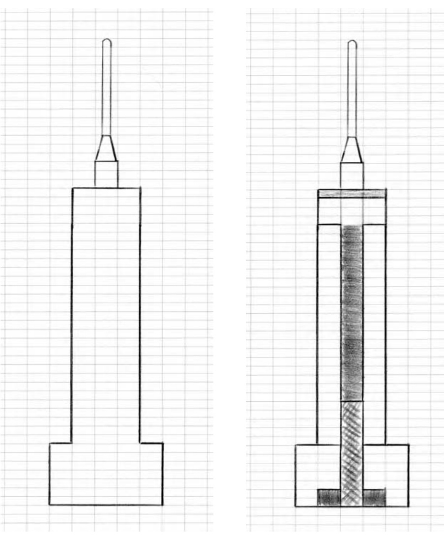
Figure 6-2: A rough outline of the building
Figure 6-3: I’ve sketched in the main features of the building.
As you can see in Figure 6-3, I’ve drawn in the main entrance, shaded an indent near the top of the tower, and added the shape of the channel that runs vertically up the center of the building. Notice that in this drawing, I’ve tried to use different shades of pencil to represent different parts of the building. In some cases, this is to remind myself that even though this is a two-dimensional drawing, it is the plan for a three-dimensional model. By shading some areas darker, I’m leaving a visual clue for myself that these will be closer to the back of the model rather than right up front. The center channel, which runs most of the height of the building, is a perfect example of this technique. It is recessed from the face of the famous skyscraper, and I want to try and duplicate that look if I can.
It’s also worth pointing out that I’m not being too careful with how my lines meet or how each area is colored in. This is just a sketch and isn’t meant to be perfect. Perfection is boring; have fun with your design sessions!
Lastly (as shown in Figure 6-4), I’ve added some boxes to represent the windows. The key word in this last sentence is represent. As noted above, microscale models will never capture every last detail and often, with a very large subject, we can’t even depict things as large as windows. You can, however, add some plates of a different color to give the sense of where windows are located.
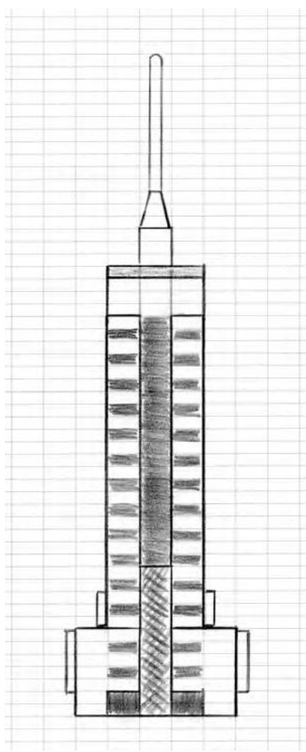
Figure 6-4: The blueprint for my micro marvel
Interestingly, this is one model that really does look good in light and dark gray. Although many of the ideas presented in this book would benefit from a splash of color, this model is one that doesn’t. The simple two-tone effect, offered by the two shades of gray, is exactly what I’m looking for.
Translating Ideas into Bricks
Now I have a plan. How does this become a LEGO model? Look at the drawing I’ve made and remember that the main idea of microscale building is to make something as small as possible and yet have it remain recognizable. Keep in mind that each of the boxes (or cells) on the design grid is the same height as a standard plate. Therefore three cells equal the same height as a standard brick (see Figure 6-5).
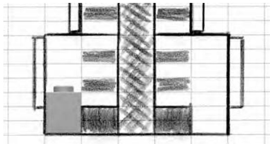
Figure 6-5: A portion of the blueprint showing how a brick compares to the design I’ve laid out
To my eye, the bottom left and right corners of my sketch (shown in Figure 6-5) look very much like LEGO bricks. Based on that assumption, I can quickly figure out what bricks and plates might work best to construct the rest of the building. In Figure 6-6, I added in some light and dark gray plates to suggest what elements I will use to build the real model.
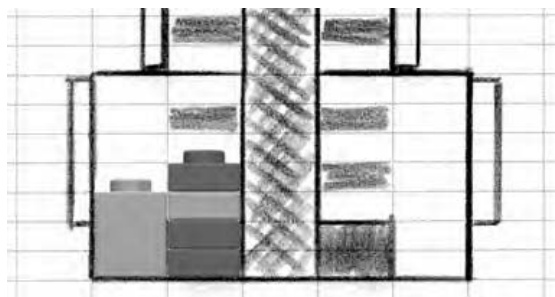
Figure 6-6: A more direct comparison between actual elements and the partial plan for the model
Although these may not be the exact pieces I end up using, they give me a sense of what types of elements I’ll need.
You can see (in Figure 6-6) that I have only represented some of the windows and even then, they are only represented by dark gray plates that I intended to give the feel of windows. As I continue to match the sketch with appropriate sized elements (based on the ’s I started with) it doesn’t take long for a little building like this to come together as the finished model you see in Figure 6-7.
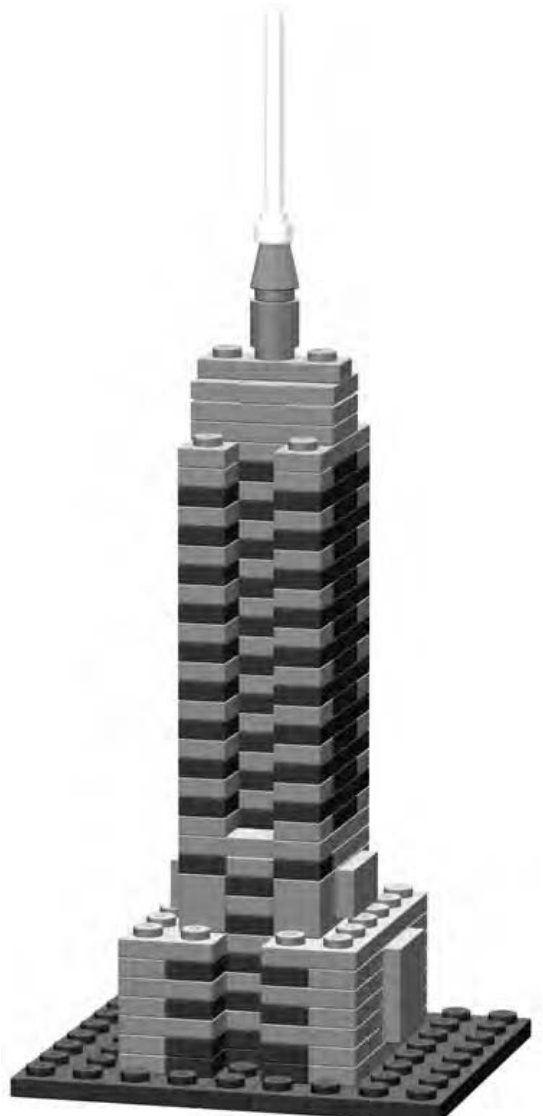
Figure 6-7: Real life brought down to size—micro size!
In the final version, I’ve included a foundation made from standard plates, though how you choose to do this (in your own version) is entirely up to you. For instance, if you were using this building as part of a larger microscale exhibit, you might need it to sit on something different—perhaps a waffled baseplate.
You’ll find that if you look carefully at this model, you can see that it’s constructed almost entirely of plates. Not every micro model will be like this but, in many cases, the smaller size of plates offers you greater creative control over your work. Of course, you may not have the right number of light and dark gray plates to make this exact replica of the Empire State Building, but don’t let that stop you from making one anyway. Try building one from just bricks to see if you can match the shape. Or try using other colors to come up with your own version. You could use white, tan, or even yellow bricks and plates to make something that at least resembles this famous landmark. Remember that was the goal—to make something that resembled this building but didn’t necessarily duplicate every last detail.
NOT
E You can find complete instructions for both the cargo ship in Figure 6-1 and the Empire State Building in Figure 6-7 at www.apotome.com/instructions.html.
Recap the Technique
You’ve now seen that building microscale models is as easy as following three simple steps:
- Sketch out the edges. Identify the outline of the object you’re building, ignore any other details. This gives you the essential shape to use as a starting point.
- Find the features. Look for major features, especially interesting shapes or patterns that help define the basic look of the object.
- Discover the details. Pick some of the smaller details to model. Be careful to select only things that are critical to the overall feel of the object.
It’s not really necessary to use paper and pencil to work out the design of your model, though you may find it very useful. Sometimes part of the fun is just digging through your LEGO bricks and working through the steps with the real elements in your hands. You can simply take apart mistakes and rebuild that portion. Some mistakes become happy accidents that end up being better solutions than the ones you originally had in mind. Either way, the benefit is that you are thinking in three dimensions and solving problems as you go.
How Do I Know What Scale I’m Using?
There are two ways to determine the scale of your micro model:
- Decide on a scale before you begin building.
- Figure out the scale after you’re done building. Let’s look at each method separately.
Decide on a scale before you begin building.
Pretend for the moment that you’re building a model to go along with something a friend is building. Perhaps you’re putting together a microscale town. The two of you agree to a scale of about 1:100. This ensures that no matter what subject matter you use for inspiration (real buildings, photos, drawings, and so on), the structures you build will have similar proportions.
NOTE Picking a scale for a project like this is really arbitrary. You want to select a scale with a fairly large difference between the two numbers. In this example, you’ve picked 1:100, but you might also find success with other scales. If you’re both building gigantic skyscrapers for a microscale city, you might want to build at an even smaller scale like 1:200 or 1:300. Remember, the bigger the second number is, the smaller the model will actually be.
Deciding upon a scale prior to building means that you will use the scale factor to know how big your model should be. For example, a real life 100- foot tall water tower would become just over a foot tall when built as a 1:100 scale LEGO model. A 25-foot corner store would be only 3 inches tall when modeled in LEGO bricks. Put together on a table, these two models would look as though they belonged to the same scene. Building to a specific scale helps you make sure such elements look right together.
Figure out the scale after you’re done building.
The second method, for determining scale, works exactly opposite to what I’ve just described. I used the second technique for the earlier Empire State Building example. I decided on the overall shape of my structure and then found LEGO elements that matched a particular part of it. Then I decided what other pieces to use based on how big they needed to be compared to those first parts I picked out. In the end, my model was about 7 inches high. Because I know that the real structure is 1,250 feet tall, I can figure out the scale using some more simple math:
(This converts the building’s height from feet into inches, since I used inches to measure my model.)
(This divides the real height by the height of my model. The result is my scale factor.)
It’s easy to see that the Empire State Building I described above was built to a scale of 1:2143. Now that’s micro!
Replacing Full-Size Parts with Microscale Stand-Ins
In many ways, microscale building is just as challenging as any other scale. You are forced to make decisions about which parts to use in what situations. Often, you might know that a particular LEGO piece exists, but you can’t use it since it’s much too big for this scale. Let’s look at two different classes of parts (wheels and windows) and see how you can simulate them at microscale without using elements actually designed to fill those rolls.
Microscale Wheels
Take, for example, most of the LEGO wheels. Many are the appropriate size for minifig or miniland scale, but they are much too large to be used as wheels for vehicles built to microscale. That doesn’t mean they can’t be used to represent something else, but you probably won’t use them as wheels. Instead you may find yourself using cylinder plates turned so that they are sitting on edge (see Figure 6-8).
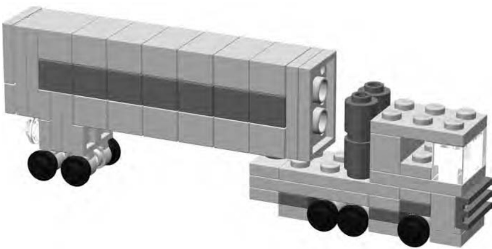
Figure 6-8: Simple microscale truck with cylindrical plates for wheels
The transport truck shown in Figure 6-8 gives you an idea not only for microscale wheels, but also provides an example of how to turn bricks on their sides to create certain shapes or patterns.
The trailer portion of the truck is created by stacking bricks on top of each other. Those stacks are then sandwiched between plates. The entire trailer section is then turned so that the studs are facing to the back of the vehicle.
NOTE For complete instructions on building the transport truck, please visit www.apotome.com/ instructions.html.
Microscale Windows
As with the wheels, many of the actual LEGO window elements will not look right when you use them as windows for buildings at this scale. You can use plates as I did in the Empire State Building earlier in this chapter, however. , for models based on smaller buildings, you can use something like the headlight brick with its side stud facing inward. Several of them, when grouped together, create the impression of a picture window for the house shown in Figure 6-9.
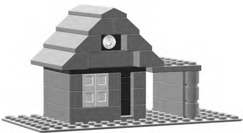
Figure 6-9: This house is much too small for minifigs but just right for a microscale suburbia.
Notice that the door to the house is merely suggested by the recessed darker area to the right of the windows. This is really just another example of the technique I used to suggest the windows for the Empire State Building. Sometimes a change in brick color or depth is all it takes to give the illusion that a particular feature exists when it really doesn’t.
Instructions for Microscale House
The little house shown in Figure 6-9 is a simple model you can probably build from pieces you already have in your collection. Figure 6-10 shows the Bill of Materials for this mini-mansion. This is followed by a series of figures (Figures 6-11 through 6-16) that show the steps you need to follow to build the house.
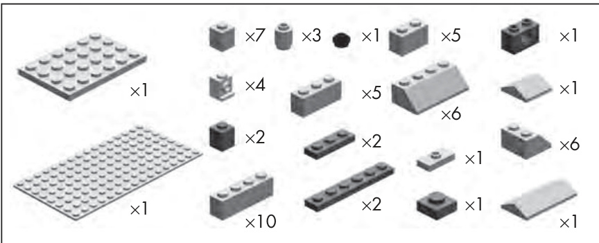
Figure 6-10: The Bill of Materials for the microscale house
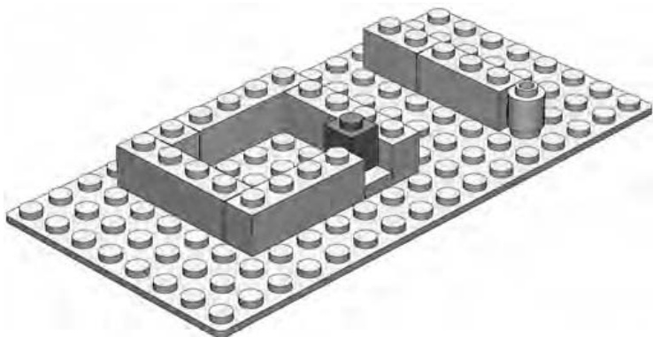
Figure 6-11: Step 1. Place the dark gray on an offset plate.
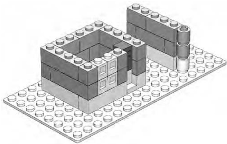
Figure 6-12: Step 2. Install the front windows, which are just headlight bricks facing backward.
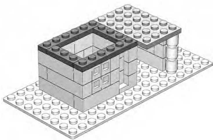
Figure 6-13: Step 3. Place a plate near the top front to help hold the windows in place.
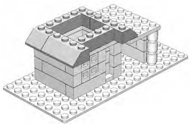
Figure 6-14: Step 4. Start the roof. The slopes on the left should hang over the edge of the wall.
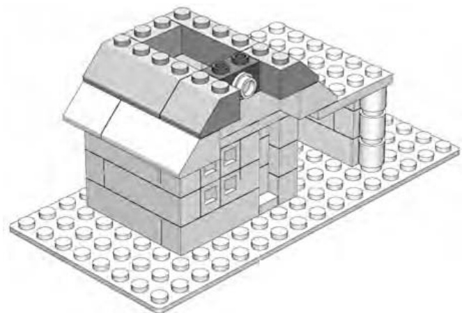
Figure 6-15: Step 5. Place the Technic brick in the top center and attach a transparent cylinder plate.
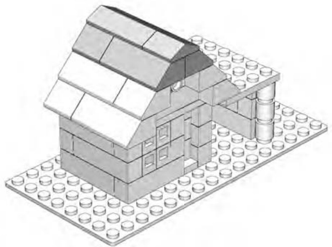
Figure 6-16: Step 6. Complete the roof with a couple of handy peak elements.
Recap of Replacement Parts
Part of the beauty of microscale models is that you don’t always need to use specialized parts to finish off your models. Simple bricks, plates, and slopes can become windows, doors, wheels, wings, trees, and so on. Use your imagination.
On the other hand, when you have specialized elements you want to use, you have many opportunities to do so with microscale models. Often, you will need a quick change of direction like that junction elements can offer. Other times, you will want interesting shapes such as macaroni bricks or interesting patterns such as grille bricks. The trick is to see the piece not just as another LEGO element but as the front end of a semi rig (as shown in Figure 6-8) or the windows of a tiny house (as shown in Figure 6-9).
Review and Suggested Subject Matter
In Chapter 5, I showed you macroscale models—the extra large versions of real life objects. I indicated that when you were looking for ideas for macro models, you might want to pick things that are very small. That way, your jumbo version wouldn’t be impossibly large.
In microscale building, the opposite theory applies. Because your goal is to build a model that is much, much smaller than the real life version, you can pick things that are naturally very large. This could mean something as large as a car, or it could mean something enormous, such as a skyscraper or an aircraft carrier.
The following is a short list of things that might make good subjects for microscale building:
Automobiles Houses Trucks Apartment buildings Buses Dinosaurs Locomotives Zoo animals Train cars Amusement park rides Spaceships from movies Skyscrapers Stores or a mall Pyramids Construction equipment Ships Hotels Aircraft carriers Castles Bridges Monuments
Of course, these are just suggestions, and like everything else in the LEGO system, there are no limits to how you apply your own imagination and creativity. Microscale models are an excellent technique to explore when your collection of LEGO elements might be limited in size, though as you’ve seen, this restriction does not have to limit the scope of your microsized LEGO world.
S C U L P T U R E S : T H E S H A P E O F T H I N G S T O B U I L D
How can you make a bunch of square bricks look round? Or oval for that matter? And how exactly do you make them to look like a dinosaur or the face of your favorite uncle? Does this ever happen? Well, hardly ever if you look at them one at a time. The trick is using them in just the right combinations to make them appear to take on rounded, oval, or other more organic shapes. That is the idea behind sculpting with LEGO bricks.
Sculpting is different from other forms of building with LEGO bricks, in that your primary goal is often to simply re-create a specific shape or series of shapes in the most realistic way possible. You can argue that the macro bricks in Chapter 5 are sculptures, and you aren’t wrong. But in those cases, the models are based on simple geometry and mathematics. Sculptured models also use those things, but they require a little more of your eye and judgment to make them successful. A sculptured model can be something as obvious as a sphere (perhaps a globe of the earth) or a sphere-like shape that you work into a larger model. You can take the techniques you learn from making spheres and use them to create the head of a large-scale minifig, an animal figure, or even part of a certain building or vehicle.
In this chapter, I’ll first walk you through the principles behind creating a basic sphere like the one shown in Figure 7-1. Then, I’ll take those lessons and apply them to another situation where the curved natural shapes proved useful.
The first sphere you build doesn’t need to be enormous in order for you to learn the techniques necessary to create it. The one shown in Figure 7-1 is only 16 studs wide and 13 bricks high. It’s just a little larger than a typical softball.
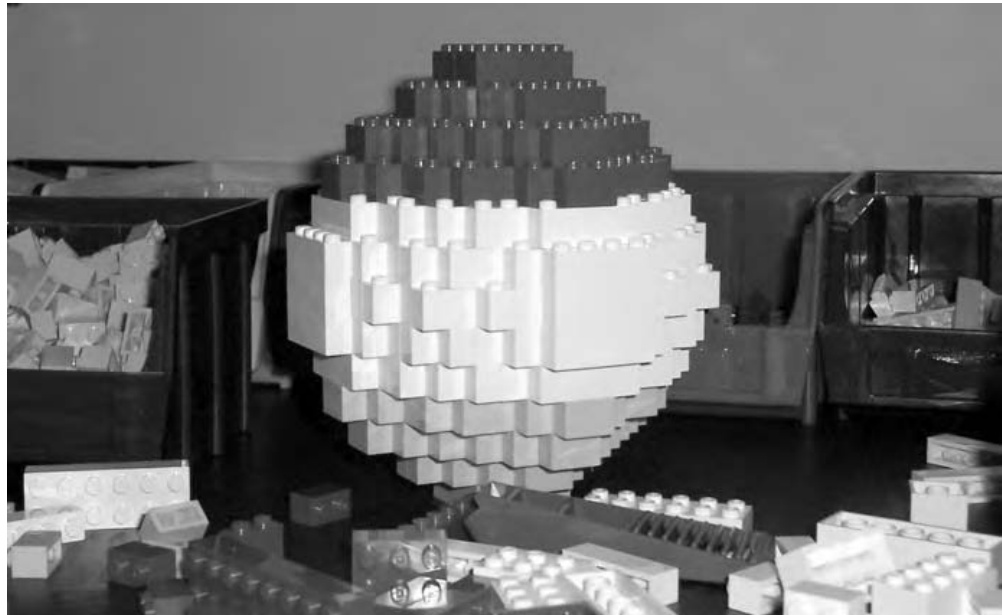
Figure 7-1: This sphere is modeled in three different colors. You can pick a color scheme like this, use just a single color, or change colors at each layer.
Spheres: Round and Round They Go
In this section, you’ll build a very basic sphere. You can create one using nothing more than standard bricks—no plates, slopes, or other special elements are required.
A sphere is really just another word for a ball-shaped object. One of the best things about a basic sphere is that you can build one with just the bricks you’ll find in a bucket of assorted bricks. You can also make your first sphere just about any size you want, depending on how many bricks you want to use. The method for producing the rounded look of the sphere remains the same if you’re building one the size of a softball or one as big as a basketball.
The degree to which you can make a LEGO globe or ball appear spherical depends mostly upon how big you build it and how many small plates you add to the mixture of parts. The larger it is, the more rounded it is likely to appear. By using more plates, to fill some of the square corners, you can also add to the circular appearance. For the example in this chapter, I’m going on the assumption that you don’t have a huge number of small plates, so you’re going to build a sphere using just bricks. It will end up looking like Figure 7-2.
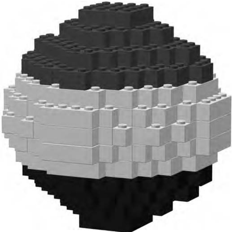
Figure 7-2: The goal. This simple sphere contains only 220 bricks, but you can use the same technique to make ones that are much larger.
As you can see, using full-height bricks alone gives you a somewhat blocky looking sphere. For this example, however, the goal isn’t to create a perfectly smooth ball, but rather to demonstrate the technique. First, take a look at the Bill of Materials for this project (Figure 7-3).
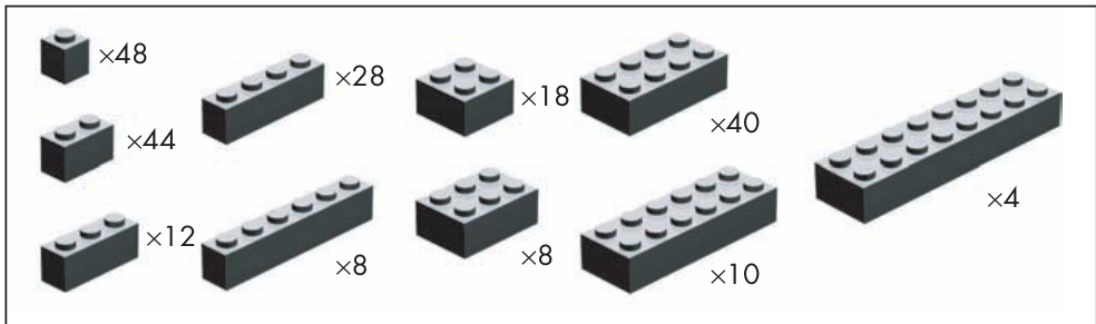
Figure 7-3: Bill of Materials for a basic sphere. This design uses common bricks and not even a lot of them!
The pieces you need to make a small sphere, like the one you’re creating in this chapter, are very common and should be within the reach of even a modest-sized LEGO collection.
Divide and Build: Two Sections Means Twice the Fun
One of the most common ways to approach a sphere is to divide the building process into two pieces: the top half and the bottom half of the model. What makes this interesting is that you start at the middle and work up to the top and then go back to the middle and build down to the bottom. Is that confusing? Take a look at Figure 7-4 to see what I mean about starting in the middle.
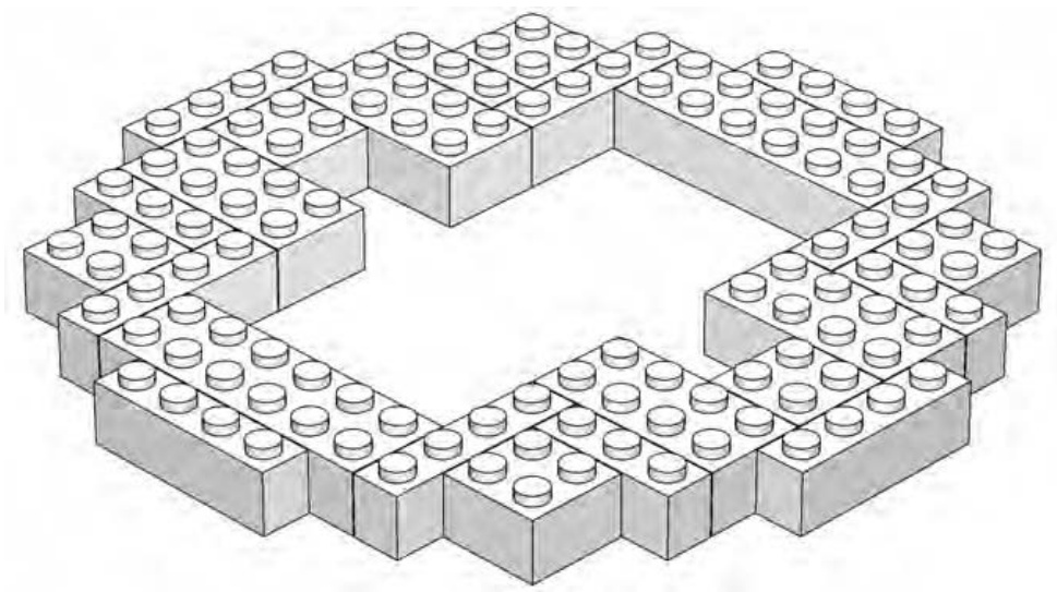
Figure 7-4: Step 1. The first layer of bricks is really the middle of the sphere.
You start building at what is essentially the equator of the sphere (if you think in terms of a planet). You lay down a jagged ring of bricks (as in Figure 7-4) that is as big around as the model will ever get. Note that for the first few steps, the model appears uneven and not very round; that changes as you get further along.
NOTE You may wish to arrange the first layer of bricks on a piece of fabric such as felt; this allows you to create the design shown in the first step without having the bricks slide around as they would on a smooth table. Once you have the second layer in place, you can remove the cloth.
Begin the second layer by using the stagger technique I discussed in Chapter 2. Remember that staggering sets one layer of bricks back from the front edge of an adjoining layer of bricks to produce a stair-step pattern.
As you see in Figure 7-5, the sphere begins to evolve very slowly at first. It doesn’t look like much right now. In fact, the second layer isn’t all that much different from the first. However, if you look carefully at the bottom of Figure 7-5, you can see some studs from the first layer that aren’t covered by the second layer. By using the stagger technique, you have begun the sculpting process, which is even more noticeable in the next step (Figure 7-6).
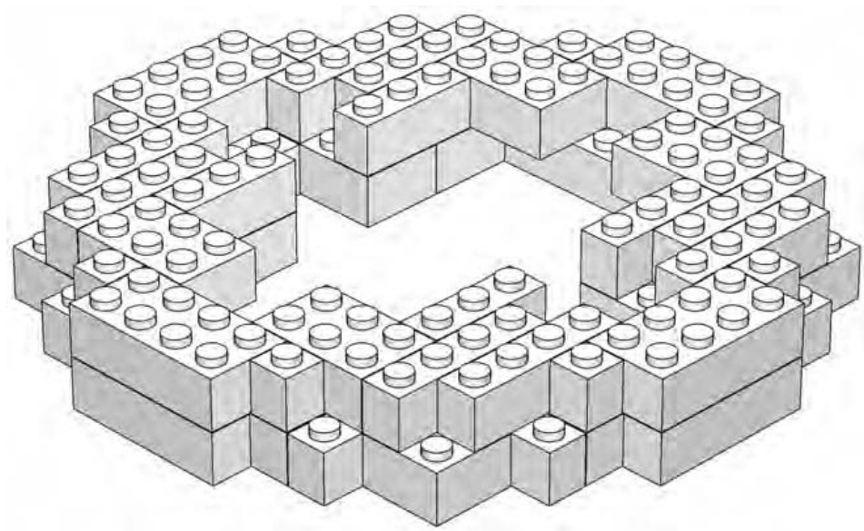
Figure 7-5: Step 2. The second layer is staggered, leaving studs of the first layer exposed.
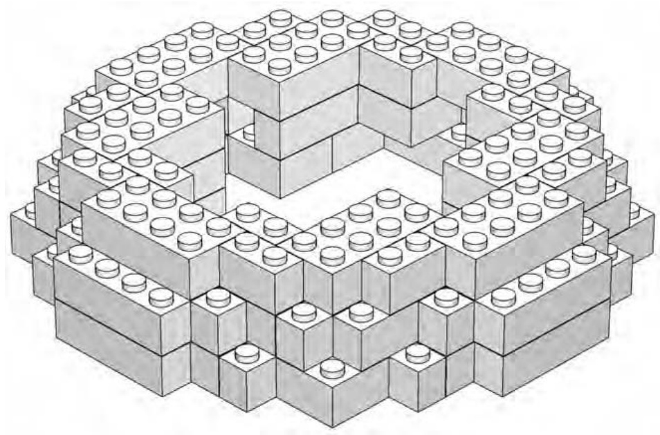
Figure 7-6: Step 3. Each layer requires fewer bricks and continues to recede from the layer beneath it.
In step three, you again leave studs of the previous layer exposed. Although the model still doesn’t look much like a sphere at this stage, it’s important, as always, that you plan ahead and keep staggering the layers as you build. Note that you don’t leave the same studs exposed each time you add a layer. By changing which studs get covered and which ones don’t, you add to the natural round shape you’re hoping to achieve. You’ll see more of this in the next three steps (Figures 7-7 through 7-9).
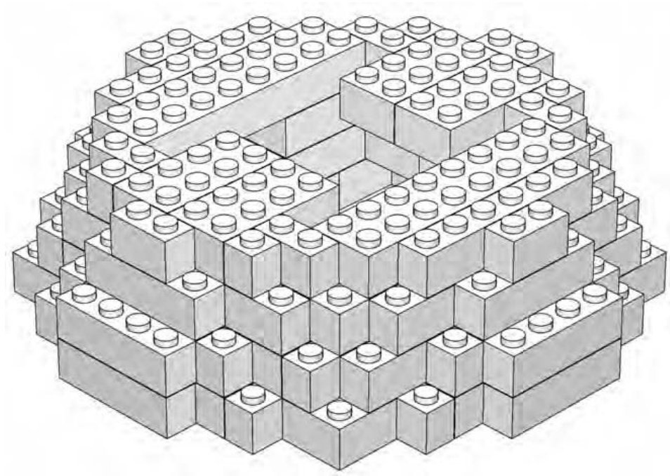
Figure 7-7: Step 4. Here you’re beginning to close in the top of the sphere.
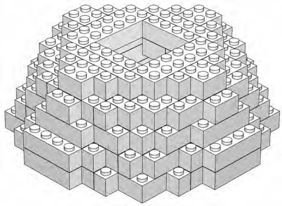
Figure 7-8: Step 5. Although the sphere is comprised entirely of standard rectangular bricks, it is beginning to seem a bit more rounded overall.
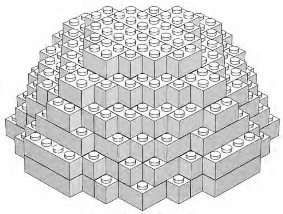
Figure 7-9: Step 6. The sphere is closed in but you’re not quite to the top yet.
As you reach the last layer of the top half of the sphere, you’ll notice something interesting (see Figure 7-10).
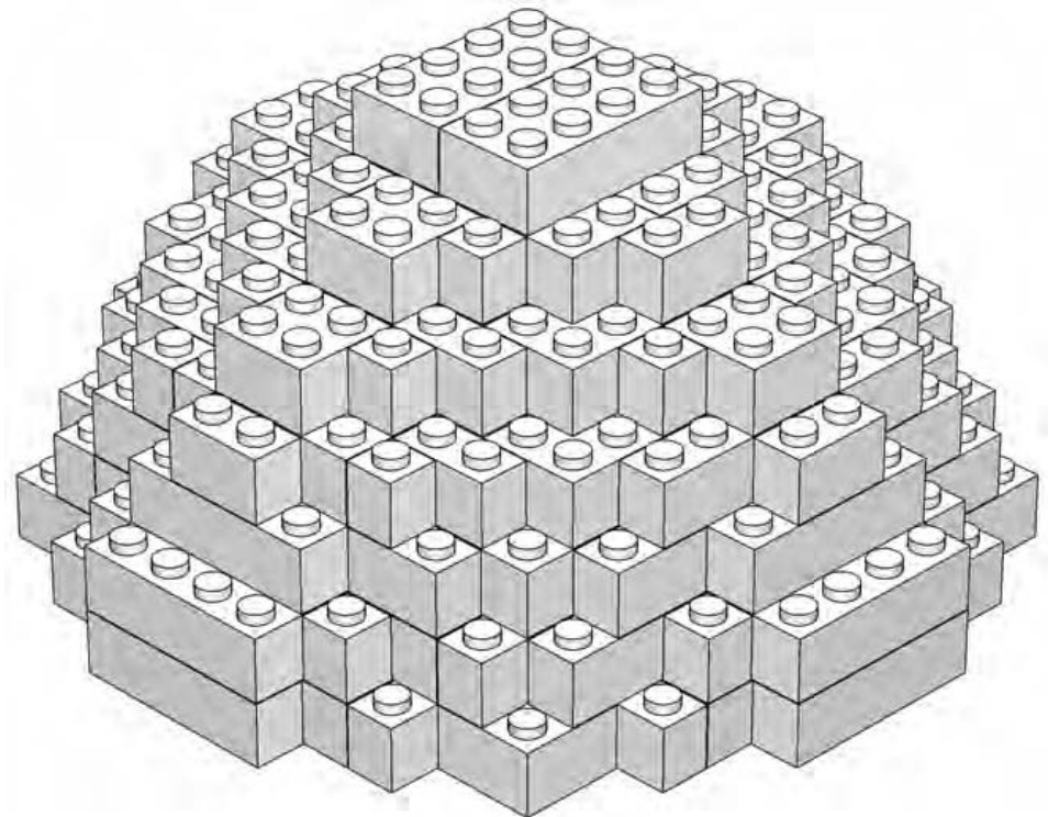
Figure 7-10: Step 7. Two bricks are all you need to cap off the top of the sphere.
In step 7 (Figure 7-10), you can see that the last two pieces you add are just bricks. Keep those bricks in the back of your mind for a moment because I will discuss them again once you’ve completed the sphere.
Step 8 doesn’t add any bricks to the model but just changes the orientation of the sphere. This is called a rotation step, and that’s exactly what you do. Take the sphere and rotate it 180 degrees until it looks like Figure 7-11.
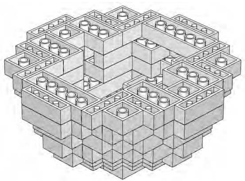
Figure 7-11: Step 8. Before you start the second half of the model, turn the whole thing so that the tubes are facing up.
You are now looking at the underside of the first layer of bricks that you placed back in step 1 (see Figure 7-4). Again, it’s important to note that you didn’t add any bricks during this process; you just flipped the sphere upside down.
For a small version of a sphere, as in this example, flipping it over is the easiest way to build the bottom half. In other words, we add to what we’ve already built, we just do it with the bricks facing studs down. When building a larger version—perhaps a globe of the earth or a life-sized soccer ball—you may wish to try another technique; build the two halves completely separate from each other. When each of the two halves is complete, you can set the upper half on top of the lower half and carefully press the two together. The example we’re building here is small enough that you can simply work on the whole thing as one unit.
In the next five steps (Figures 7-12 through 7-16), you can see that you follow a pattern similar to what you’ve already been doing, except now, instead of leaving studs exposed on each layer, you leave portions of the bottom of bricks uncovered. It’s also interesting to note that as you build the bottom half of the sphere, you are placing the bricks on upside down as well. It’s not that this technique is dramatically more difficult, but because the orientation is different, you may find that each brick requires just a little more thought to place it on the model.
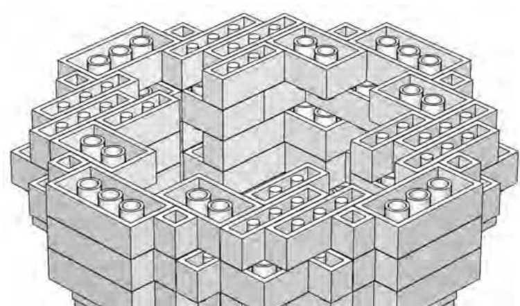
Figure 7-12: Step 9. You’re still staggering bricks; it’s just that you’re now doing it upside down. But don’t worry: it’ll all work out in the end.
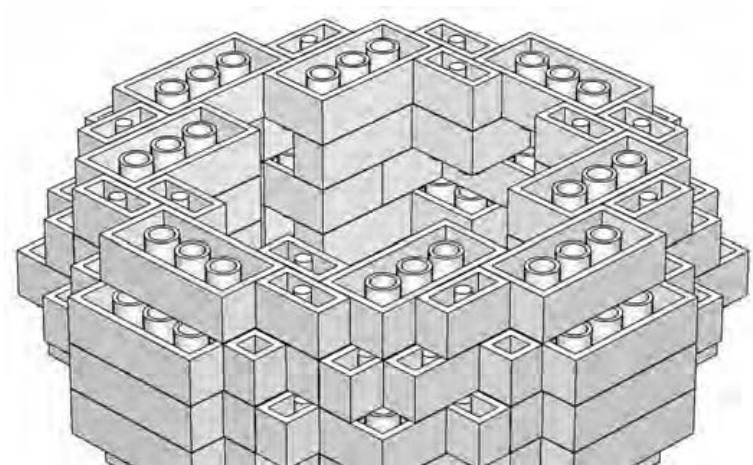
Figure 7-13: Step 10. In Chapter 2, I noted that staggering also involves a bit of overlapping. The same holds true here.
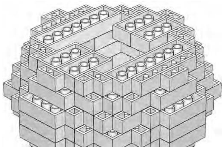
Figure 7-14: Step 11. Watch the placement of your layers carefully on a model like this. The way in which you’re staggering is exactly what’s giving the sphere its shape.
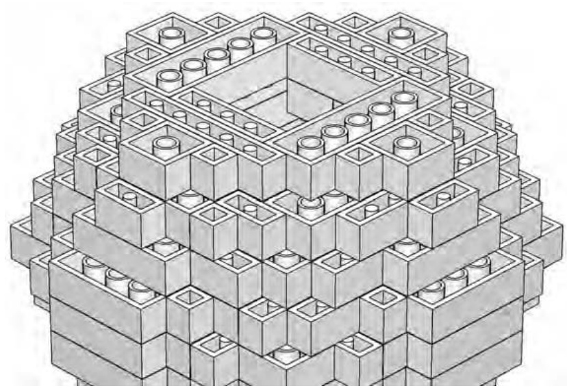
Figure 7-15: Step 12. The small opening that remains is certainly square, but the next step helps solve that problem.
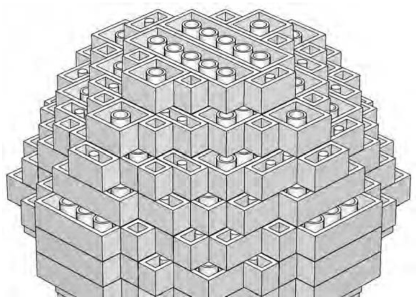
Figure 7-16: Step 13. Close in the bottom with exactly the same combination of pieces you used back in step 6.
You add the final two pieces in step 14 (Figure 7-17).
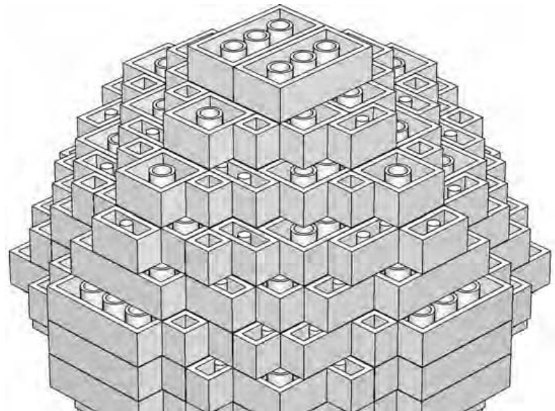
Figure 7-17: Step 14. bricks once again give you the finishing touch you are looking for.
Just as with the two pieces on top of the sphere, the last pieces of the bottom are two bricks. Remember I asked you to keep those in mind? Here’s what I want you to notice. Compare the two ’s on top (Figure 7-10) with the two ’s on the bottom (Figure 7-17). Exactly the same, right? Now compare those bricks with the flat areas found on the “sides” of the sphere. In Figure 7-18, I’ve tried to highlight this in a close-up.
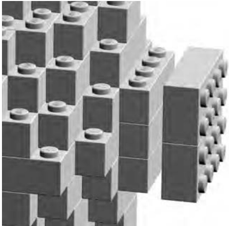
Figure 7-18: Matching the size of your top with the smallest areas on the sides of the sphere will help you get a sense of just how “round” you’ve been able to make your sculpture.
You can see that two ’s are almost the same size as those flat areas along the equator. This is what helps you to know that your sphere is the right size and shape. Remember that the top and bottom of your sphere are represented by two bricks—all facing studs up. The four “sides” of your sphere (where the sides round off to their smallest face) are made up of three layers of bricks, but it’s the portion of their sides that is flat that is most important. Those outward facing sides (as seen in Figure 7-18) should be just about the size of the outward facing surfaces of the two bricks on the top and bottom. Having them nearly the same is what helps to give the sphere its rounded appearance even though it’s built entirely of bricks that are not round at all.
Beyond Spheres: Sculpting Other Subjects
In both Chapters 3 and 5 we looked at things that had very straight sides and were primarily constructed using the overlap technique. Sculpting, on the other hand, relies more on the stagger technique you have been using so far in this chapter. The example you built to learn about sculpting was a simple sphere. But there are only so many times you would ever need to build something so plain. More likely, you’ll want to sculpt an animal, a statue, a cartoon character, or perhaps some extraterrestrial being born in your imagination.
Choosing a Subject
For this section, I tried to find a subject that would be familiar and yet still offer interesting ways in which to build it as a LEGO brick sculpture. I chose the famous Great Sphinx of Giza. It has overlooked the sands of Egypt for thousands of years. The real Sphinx is itself a sculpture, so this model is then a sculpture of a sculpture. You can see the model I created in Figure 7-19.
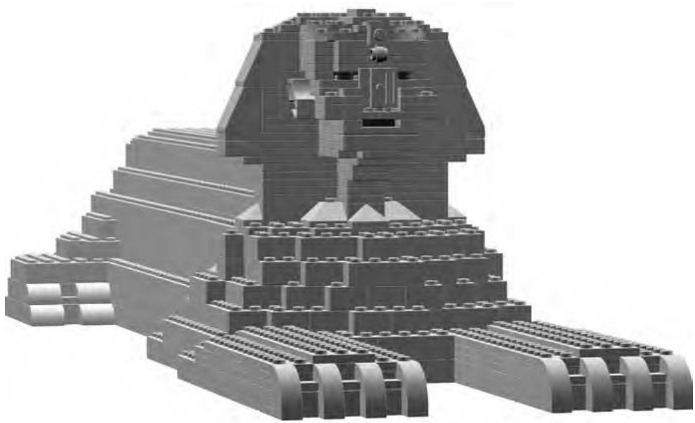
Figure 7-19: The Sphinx combines the head of a pharaoh with the body of a lion.
As with the Empire State Building example from Chapter 6, the first thing I did was look on the Internet to find pictures of the Sphinx. Unlike what I did with that micro model, I did not use the design grids for planning the construction of the Sphinx. Rather, I went on the look and feel of the work as it progressed. Remember, there is no right way or wrong way to tackle a project like this. If you prefer to use the grids to help plot your design, that is perfectly acceptable.
Aside from the fact that it’s so well known, I picked the Sphinx for two other reasons. First, it is a relatively simple shape to attempt to copy in LEGO elements. By contrast, a sculpture of a knight riding a horse would have presented much greater challenges due to the larger number of shapes, curves, and angles required.
Second, it is essentially just one color and therefore allowed me to concentrate on shape alone, rather than having to also select proper colors as I went. What color should the Sphinx be, though? To make it look very accurate, I modeled it in tan colored bricks. If you want to build your own but don’t have enough of those elements, you might want to think of an alternate color such as white or yellow. Although not as realistic as tan, these colors would be less cartoonish than if you build it out of red or blue.
Getting Started on the Sphinx
In Chapter 6, I talked about finding a unique feature on the object you are using for inspiration. In the case of the Sphinx, most people recognize the human-like head with a Pharaoh’s headdress. This is the starting point I selected. If you were building the model on your own, you might decide you’d rather build the body of the statue first (a form based on a lion at rest) and work your way up.
NOTE For complete instructions to build the Sphinx model, visit www.apotome.com/ instructions.html.
For the example in this book, I built the head until it looked right and then created a body to match. I made this decision because I was more concerned about capturing the look of the head than I was about getting the body exactly correct. After all, if people don’t recognize the head, then the rest of the sculpture may not matter anyway.
Analyzing the Angles: Building the Head
In an attempt to copy the head of the statue, I first looked at the angles that make up the headdress. It is the headdress that helps define the shape of this part of the Sphinx, and getting it to look realistic was important to the success of my sculpture.
The sides of the headdress slope at an angle of around 55 degrees. That’s a little less than a 65-degree standard LEGO slope, but it’s pretty close. (For more about this slope piece, refer to Appendix A, the Brickopedia.) After I selected these pieces to start with, I began building the head.
You can see the Sphinx’s head starting to take shape in Figure 7-20. As the sides of the head began to rise, I also wanted to build outward to capture the face. Remember, a sculpture needs to look right in all three directions: length, width, and height. I couldn’t just build a flat face because the sculpture also needs to appear accurate when viewed from the front or the side.
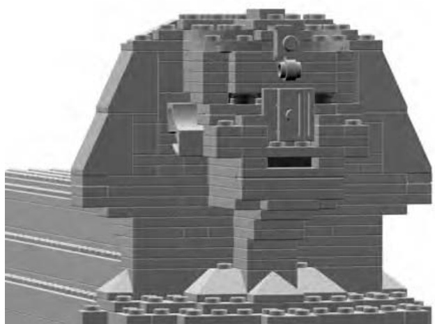
Figure 7-20: The head and headdress of the ancient statue
In Figure 7-21, I’ve shown the head rotated 90 degrees so that you can see the face coming to life. Does it have to be perfect? No, not at all. This was a relatively small model, so trying to duplicate every last detail would have been very difficult. It is important, however, to capture the overall appearance of the object and let the mind of the viewer fill in the remaining details.
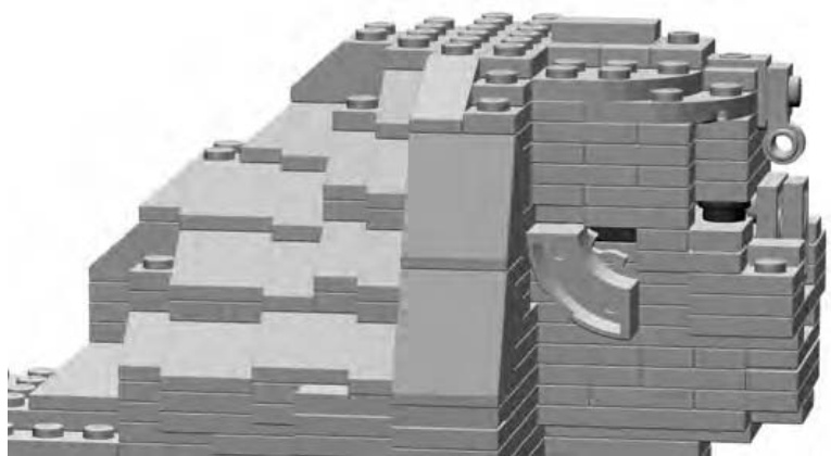
Figure 7-21: Sculptures of faces challenge you to think in three dimensions.
Special Features: Special Techniques
The actual Sphinx has several unique features that I wanted to capture. Each presented its own challenges with regard to parts selection and building techniques.
The Nose
One of the features I did simulate was the missing nose on the real Sphinx. Notice in Figure 7-22 how I used plates with their undersides facing outward to give the impression of uneven stone where the nose was once attached.
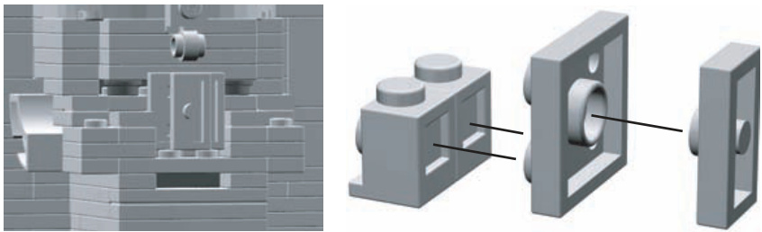
Figure 7-22: Note the unique ways each piece connects to the others. The three pieces on the right join together to become the nose, as you can see on the left side of this illustration.
You can see in Figure 7-22 that I took advantage of the unique geometry of LEGO studs and tubes. The offset plate (to the far right of Figure 7-22) fits perfectly into the tube of the plate next to it. The plate, in turn, fits snuggly into the open sides of the headlight bricks next to it.
The Ears
The ears, like the nose, are another example of how you can turn LEGO elements in directions other than with their studs pointed upward.
In Figure 7-23, you can see a macaroni brick with its underside facing away from the side of the head. The more natural curved shape of this element helped add some character to the face of my Sphinx model.
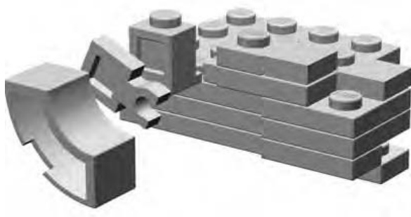
Figure 7-23: A blown-up view of the ear so that you can see how the pieces attach to the side of the head.
The Paws
The large paws, stretching out from the Sphinx, are mostly rectangular but do have some curved toes at the end.
To create these more natural shapes, I tucked a half-arch piece under a half-arch (Figure 7-24) to represent each toe. As you can see, the smaller of the two parts nests perfectly under the larger half-arch, creating a less blocky appearance.
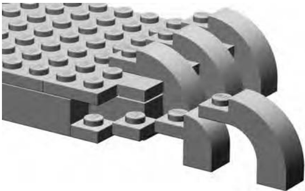
Figure 7-24: Curved pieces like these half-arch elements are naturally pleasing to the eye and add character to this otherwise rectangular section of the model.
The Headdress
In Figure 7-25, I’ve turned the head yet again so that you can see the back of the Sphinx’s headdress.
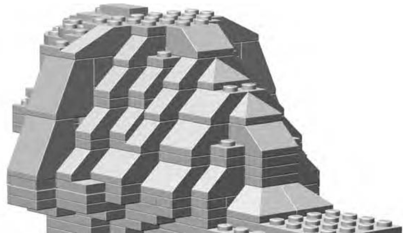
Figure 7-25: The back of the headdress was an exercise in sculpting with slopes. I didn’t follow any hard-and-fast rule. I just kept adding and removing slopes, changing the type of slope I was using, and generally just working at it until I had the natural look I wanted.
When you actually sit down to build any sculpture from real bricks, you will also find yourself turning it to various angles to make sure it looks right from every direction. In the case of my Sphinx, standard slope elements, in several different variations, proved immensely useful for sculpting the back of the headdress.
Figure 7-25 shows the headdress blending into the body. It’s important to point out that I didn’t get the look I wanted on the first attempt. You probably won’t either when working on your own sculptures. Don’t be afraid to take parts off the model, move them around, or swap in new parts until you have sculpted the shape you want.
Building the Foundation Last
There are certainly many times when you will want to start at the bottom of a model and work your way up. For example, you’d probably apply this approach to most buildings. In such cases, you will find it much easier to build successfully if you build a solid foundation and work your way up, building the walls next and finally the roof.
In the case of my Sphinx model, I chose to go the opposite route, but for a reason. I built the head first to make sure my replica looked the part—that it looked like the head of the Sphinx. Then I built a body to match the head.
Once the head was completed, it was easiest to work on the shoulders next, then the back, and finally the legs. When building downward from the neck, it was easier to make the body match the scale at which I built the head. Since I wasn’t overly concerned with making a perfect representation—I settled for reduced detail at this small size—it wasn’t critical that I work out the exact scale like we did for the train station back in Chapter 3. Instead, this was more an exercise in eyeballing the model to make sure it has the look I was after.
The shoulders and neck of the Sphinx are primarily a combination of standard bricks, plates, and slopes too. Never overlook the inherent flexibility of these basic pieces; this is one reason that they have long been the heart of the LEGO building system.
As I continued to build the lower body and legs (see Figure 7-26), I also continued to go back to the pictures of the Sphinx I found on the Internet. Images of real life objects, buildings, vehicles, and so on can be enormously beneficial when you’re building LEGO models. If you are ever able to see, in person, the thing it is you wish to build, then be sure to take some photographs while you are there. Capture the subject in a wide shot, to get its overall size and shape, but also be sure to get close-ups of details and features that you want to replicate. This research technique is used by Master Builders who work for the LEGO company. Why not use it to make your work more realistic and natural?
The completed Sphinx model is shown in Figure 7-26. Notice that I made a conscious decision to leave some areas of the model uneven; not every edge is perfectly square. This was an attempt to reproduce some of the wear and tear that time has taken on the actual Sphinx.
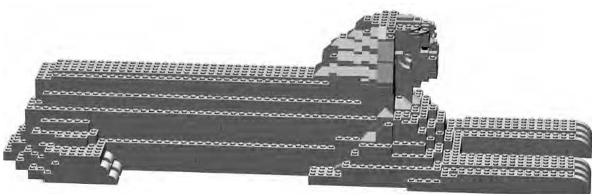
Figure 7-26: The body of my Sphinx is basically a box shape with staggered sides. It’s the head and face that really brings the sculpture alive.
Review: Sculptures—In the Eye of the Builder
When sculpting real life objects, look for edges that can be rounded by either staggering some bricks (as in the sphere example) or by using slopes. Also keep in mind that things like faces, statues, or mountains may not be completely symmetrical. That is to say, one side or another may be shaped slightly differently than the others. If you can reproduce some of that organic quality, it will add a great deal of depth to your creations. The stagger technique will help you greatly when trying to reproduce more natural shapes.
Remember also that I built the Sphinx model using trial and error and worried more about overall look and feel than about strictly following a blueprint. On the other hand, the sphere, required some careful planning to make sure that the shape was very precise. You will want to use a bit of both techniques to build sculptures. How much of each you use will depend on your subject. In the end, it comes down to how the model looks to your eye; this is what decides whether or not it has been a successful build.
M O S A I C S : P A T T E R N S A N D P I C T U R E S I N B R I C K S
You might be wondering, “Just what is a mosaic?” The title of this chapter offers a clue. The term mosaic is used to describe artwork consisting of patterns or pictures created on a surface using stones, tiles, bricks, or even glass. You’ve probably seen an area above a kitchen sink that displays a pattern made up of small ceramic tiles glued to the wall. That is a mosaic.
Since the core of the LEGO system consists of small bricks and plates that you can easily use to form patterns or illustrations, LEGO is an ideal medium for creating mosaics.
Two Types of Mosaics
LEGO elements offer you two different ways in which to create mosaics. The first style, known as studs-out, is formed by attaching smaller bricks or plates (often ’s or ’s) to a baseplate with their studs exposed, or “out,” where you can see them. Figure 8-1 shows a mosaic pattern created in this manner.
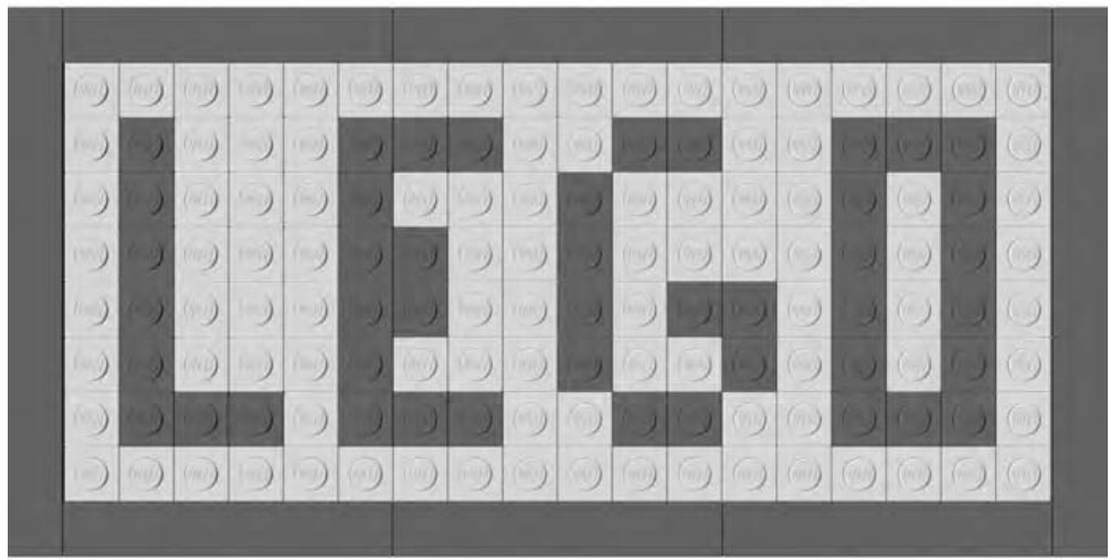
Figure 8-1: The elements that make up the main image are facing studs-out, whereas the border of this small mosaic is made up of standard tiles.
In Figure 8-1, you can see that the studs on each piece face out toward the viewer. Studs-out mosaics tend to be blocky in appearance but are fairly easy to plan and build. Later in this chapter, I’ll show you a couple simple ways to turn an image into a mosaic.
The second way to make a LEGO mosaic is to use something known as the studs-up approach. In this case (shown in Figure 8-2), the pattern is created by viewing the bricks and plates from the side so that their studs are all pointed up toward the top of the picture.
Figure 8-2: You can use studs-up mosaics alone to create interesting, stand-alone, artistic pieces, or as part of a larger model to add lettering or other images.
A more advanced version of this technique involves turning some of the plates (and sometimes tiles) by 90 degrees to allow for more subtle shapes. In this chapter, we’ll look at the basic technique but also create a more complicated pattern.
What Can You Do with Mosaics?
The mosaic technique is very much like other building methods I’ve already shown you such as overlapping, stacking, and staggering. On its own, it’s just another way of putting LEGO bricks together. It’s where you decide to use the technique that makes it truly effective.
When you use it alone, the mosaic technique can help you make interesting and artistic panels that you can display just as you do paintings or photographs. Such mosaics may be repeating patterns or may be images you have copied from real life. In these types of mosaic, the end result stands alone and does not require anything else to make it complete.
Another way to use this form of building is to incorporate a mosaic section into a larger model. For example, you may want to spell out the name of a company on the side of a cargo truck or a locomotive. Or, you might want to simulate a painted mural on the side of a downtown building. In other words, you would use the mosaic technique to enhance another model, the remainder of which would be built with the other techniques you already know.
How Big Should a Mosaic Be?
The size of your mosaic depends on what you intend to do with it. As noted earlier, the technique can have several applications. You might build a mosaic that you just want to be a display piece (such as an image of your pet or favorite car) on a stud baseplate or perhaps on the larger stud version.
On the other hand, you may want the mosaic portion of a larger model only to be a small section of a wall or the side of a vehicle. I’ll show you examples of both uses in this chapter.
What You Need to Make a Mosaic
As noted earlier, a LEGO mosaic can be any size you like. If it is an image you want to display that you’ve made with the studs-out technique, it is likely to be the size of whatever baseplates you have available. Figure 8-3 shows a picture of the two most common large waffle-bottom baseplates that LEGO makes.
The smaller, darker baseplate is studs, whereas the larger one is studs. For the remainder of this section, you’ll focus on creating works assembled on the version.
In addition to a baseplate, you need lots of elements to make a mosaic. If you can obtain enough standard plates in this size, then you can create a very thin picture. Otherwise, you’ll more often build your studs-out mosaic using standard bricks. Although it will be thicker from front to back, the resulting image, as it appears to the viewer, will be just the same when viewed from the front. You may also want to use other standard bricks, or even peak elements, to create a frame around your image.
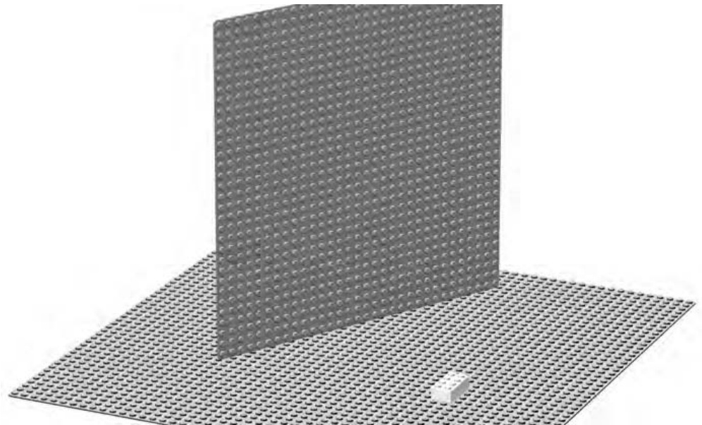
Figure 8-3: The small white square near the bottom center of the picture is a standard brick. This gives you a sense of the size of the baseplate.
To create a studs-up mosaic, you again need lots of small elements ( bricks and plates), but you also need whatever other pieces are required to fit the mosaic section into the larger model you’re building.
Designing a Studs-Out Mosaic
In Appendix B of this book, you will find information regarding model Design Grids. Take a moment now to visit the website for this book (www .apotome.com/grids.html) and print out at least one copy of Design Grid #1.
You’ll find that this grid looks very similar to traditional graph paper, except that each square is exactly the size of a standard LEGO element as seen from above, looking down on the stud. To plot the location of different colored bricks, simply shade in the squares, much like I did when planning the Empire State Building model in Chapter 6.
For the examples in this chapter, I’ll be using only the colors gray, black, and white. For your own models you can, of course, use any colors at your disposal.
Geometric Patterns
As a simple way to get started with mosaics, you might want to try a geometric pattern. Like the tiles above a kitchen sink, this technique involves repeating one or more designs to create a pleasing image.
The Design Grids can be used to plan this type of mosaic or you can just build one freehand, developing the pattern as you go. You may wish to try a repeating pattern at first. Outline a small set of squares (perhaps , , or ) such as those shown in Figure 8-4. Then use this small area to create a patterned tile.
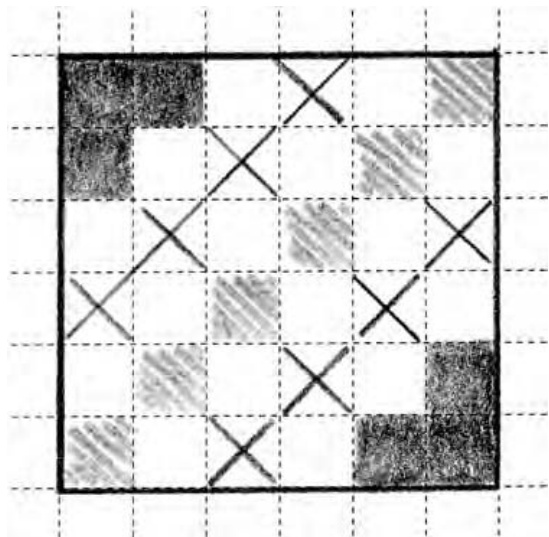
Figure 8-4: Planning a mosaic tile doesn’t need to be complicated. This rough sketch took only a couple of minutes, but it gave me a good idea of what the final product would look like.
The next step is to use your sketch as a pattern to create the actual mosaic out of LEGO pieces. As noted earlier, you can use a stud baseplate if you have one, or you can even use smaller waffleplates and simply join them together.
In both Figures 8-5 and 8-6, you can see there’s really nothing complicated about actually building the mosaic. It’s simply a matter of attaching your elements to a baseplate.
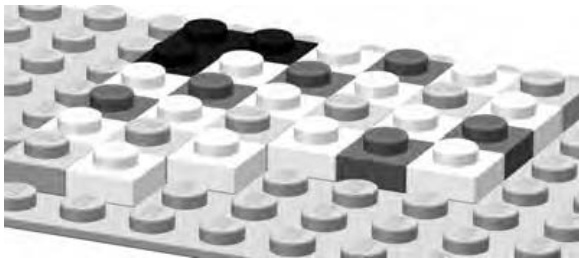
Figure 8-5: If you have enough plates, you can make a very thin mosaic. If not, you can always use bricks instead.
The mosaic in Figure 8-5 was made using standard plates. Compare that to Figure 8-6, which was made using standard bricks instead. From this point forward, I will refer to bricks when discussing this technique, since they are much more common and inexpensive than plates.
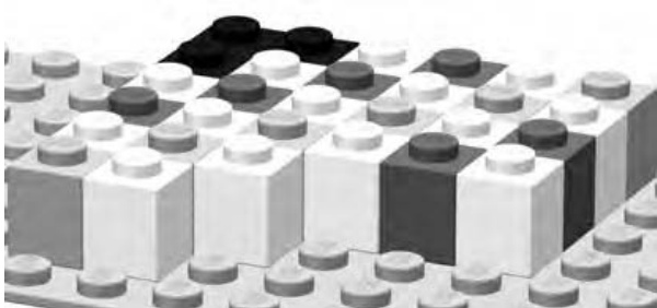
Figure 8-6: bricks work just as well as plates when you are creating a studs-out mosaic. Your art is a bit thicker, but in the end, it looks just the same when viewed from the front.
When you’re done setting down the elements onto the baseplate, your first tile might look something like the pattern shown in Figure 8-7. This isn’t a complete work of art (yet!) but rather one of many sections that can work with others to form a final presentation.
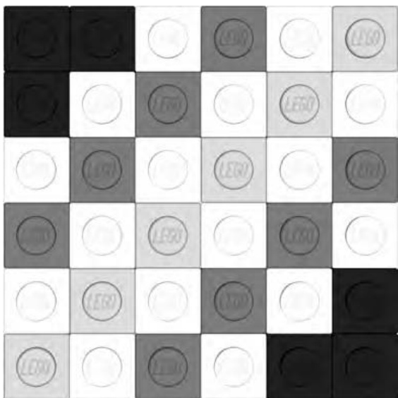
Figure 8-7: A small grouping of pieces gives you a tile that you can then repeat to make even more complex patterns.
Compare the sketch in Figure 8-4 to Figure 8-7, and you’ll see that I’ve replaced the different shaded squares with various colors of LEGO pieces; I’ve worked with black, white, and two different shades of gray. Of course, when you’re creating your own mosaics, you can use any of the brighter colors you have in your collection of elements.
Remember earlier I mentioned using repeating patterns (like tiles above a kitchen sink) to create larger mosaics? Take a look at Figure 8-8, and you’ll see what happens when I repeat the pattern I just created.
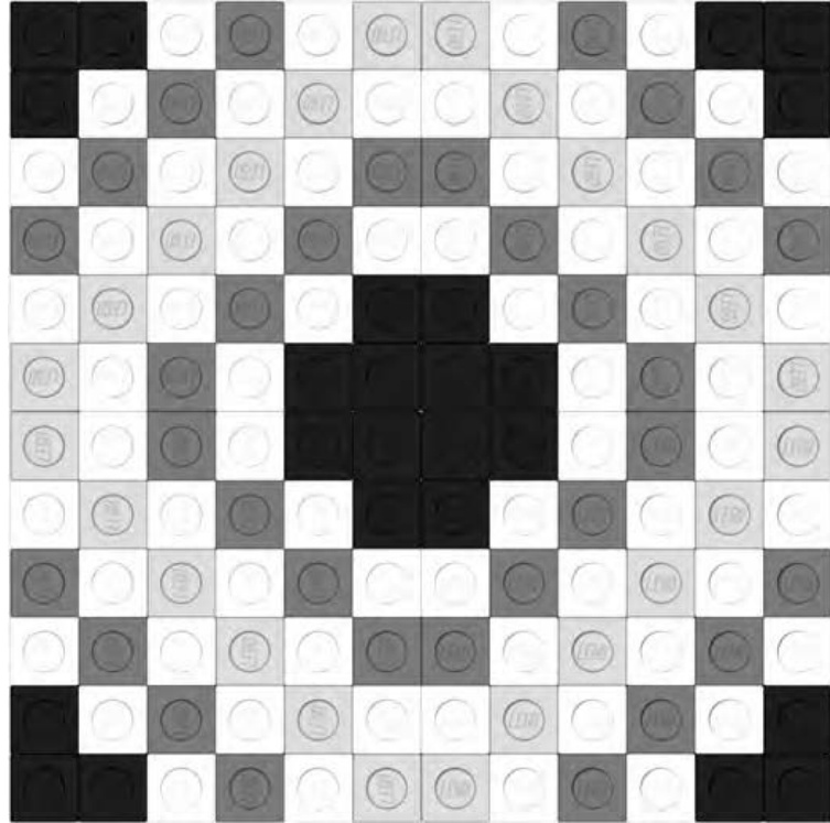
Figure 8-8: Four tiles grouped together to make a larger mosaic. This pattern can then be repeated to make even bigger images.
Figure 8-8 is a mosaic made up of four copies of my tile from Figure 8-7. Notice that I’ve rotated a couple of the tiles to make the black corners meet in the middle. This helps create a more pleasing pattern and also one that can be repeated as many times as you like. I can in turn create four more copies of the pattern and place them next to the first four (see Figure 8-9).
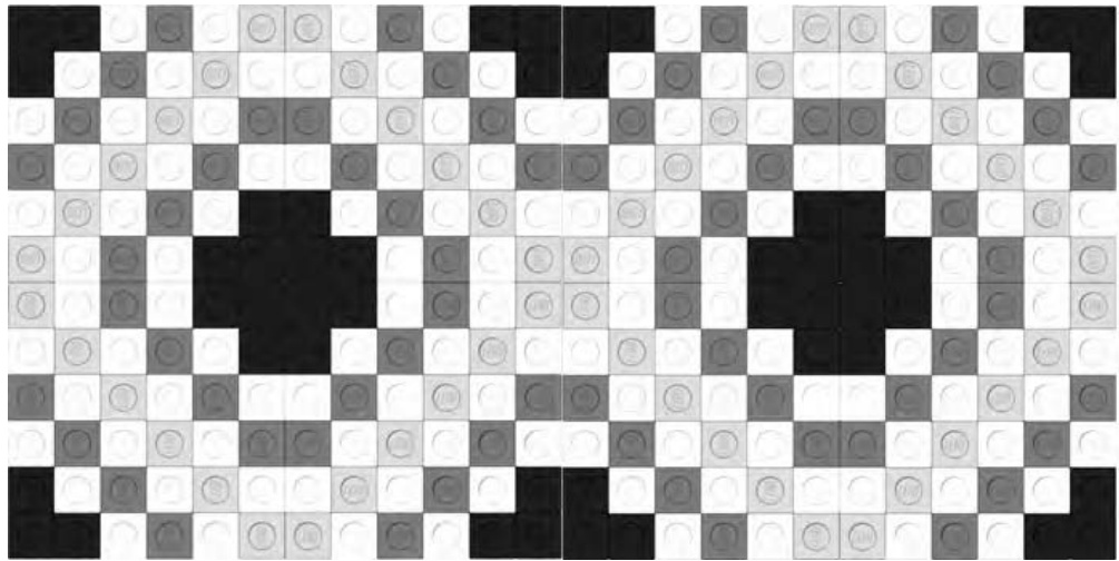
Figure 8-9: Eight copies of my original tile are aligned to create a repeating pattern.
In Figure 8-9, you can see that the pattern continues to match and repeat. This could become the ballroom floor for a minifig-scale hotel. Or, as noted earlier, you can simply repeat it until it fills a large waffleplate and becomes a pleasing image of nothing but patterns. Try designing your own tile pattern. Then see what it looks like when you put multiple copies side by side.
Copies of Pictures
If you want to try something a bit more complicated, you can tackle a photo mosaic. These, as the name suggests, are LEGO pieces arranged to look as much like an actual photograph as possible. There are a couple of interesting ways to create this type of mosaic. The first, print and trace, is a fairly low-tech approach that also gives you a bit of room to add your own artistic flair to the project. The second, converting to pixels using a computer, is a more sophisticated approach, but it can still result in natural and interesting results.
Print and Trace
To make this technique work, you’ll need two things.
-
A decent picture of what you want to turn into a mosaic. If it’s a digital picture, make sure it’s loaded into your computer. If it’s an actual printed photograph, first scan it in so that you can manipulate it digitally. You’ll also need to print the picture you’ve decided upon, but before you do that, there are two more things you’ll want to do first. a. Crop the image so that the picture is more or less square on all sides. b. Resize the image so that the length and width are as close to inches (162 millimeters) as you can get. This assumes you are attempting to make a stud mosaic.
-
A copy of Design Grid #2 (see Appendix B). Preferably, this should be printed on paper that is not too thick or opaque.
To create the pattern for your mosaic, just place your printed image under the copy of the Design Grid that you printed out. You may wish to staple or paperclip the two sheets together so that they don’t slide apart. Now simply shade in the squares on the Design Grid to match the light and dark patterns you see through the grid. In Figure 8-10, you can see that I’ve applied this technique to an image of a fish that I found on the Internet.
Although the studs-out technique tends to be a bit blocky looking, it does work reasonably well for subjects with strong shapes, outlines, or patterns. When selecting a picture to use, try to make sure that the important part of the image fills as much of the space as possible. In other words, a close-up of a friend’s face will work better than a picture of a car driving on a bridge far off in the distance.
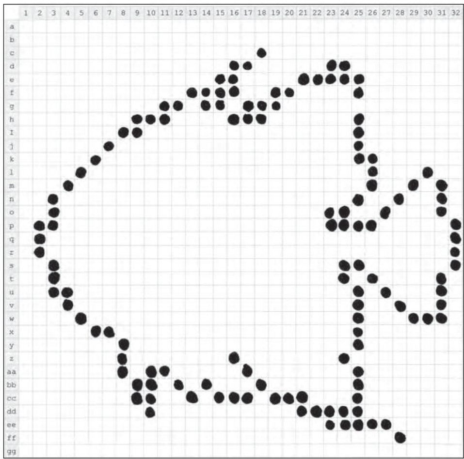
Figure 8-10: An angelfish begins to emerge from the design grid. Preplanning gives you some sense of what the final mosaic will look like.
In Figure 8-10, you can see that the illustration of the fish I used mostly fills the grid. That gives me as much space as possible to use when defining the outline of the object in the image. Keep in mind that with a studs-out mosaic, you are not going to end up with smooth, flowing lines. For certain, your mosaic image will end up being a bit rough. The challenge then is to see just how natural you can make your design despite the handicap of doing it all with square pieces.
NOTE You may notice the numbers along the top side of the Design Grid and the letters along the left side. Refer to Appendix B for more information about these markings.
In Figure 8-11, I’ve begun to add some of the details within the outline of the fish. I’ve used different shades of pencil and even different ways of shading the squares to suggest differences in color.
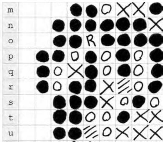
Figure 8-11: A close-up of just the face and mouth of the angelfish. Coloring within the lines is optional.
You may wish to use the legend printed at the bottom of the Design Grid to remind yourself which symbol represents which color. As you can see in Figure 8-12, it’s easy to put it to use. Simply draw a symbol (or shading pattern) in a box and then write the name of the color next to the symbol it represents.
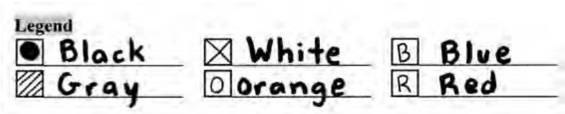
Figure 8-12: It takes only a minute to jot down the legend to go along with your design. This helps make the actual building process of your mosaic much more enjoyable.
It’s worth pointing out that it really doesn’t matter how neat your design looks on paper. By that, I mean don’t worry if you don’t shade in each of the boxes with computer-like precision. The Design Grid version is just a rough sketch of what your final LEGO mosaic will look like. The only important thing is that you can tell what color you intended to go in each square. No one will see the paper version, so be as messy as you like.
NOTE It can sometimes be a challenge to see through the Design Grid to know which boxes to shade. If you’re having trouble, try holding the original image up to a window; then place the Design Grid on top of it. The light shining through should help you see where you want to sketch in your mosaic. Need a similar trick you can use when the sun’s not shining? Try finding a translucent plastic storage container—like the one in which you might store LEGO bricks—and turn it upside down. Then, as before, put the original image, with the Design Grid on top. There should be enough light filtering up from below to help you see what the original image looks like.
Finally, in Figure 8-13 you can see how my angelfish design turned out. Although it’s far from photorealistic, it’s a reasonable representation of my subject matter.
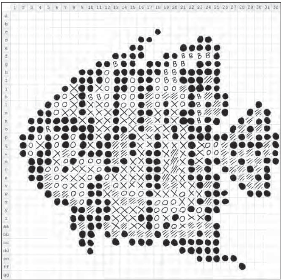
Figure 8-13: Although a bit rough around the edges, the blueprint for my fish mosaic still gives me a good starting point.
As you translate your paper design into actual LEGO elements, be sure to make changes as needed. The pattern you’ve drawn on the Design Grid should provide you with an excellent starting point, but you don’t need to follow it exactly. Sometimes seeing the actual pieces on the baseplate will trigger the desire to make changes; make as many as you feel you need to until the picture feels right.
If you’re having trouble seeing what the mosaic looks like before it’s complete, try one of two things:
- Set your semifinished work on edge and step away from it. Most mosaics are best viewed from at least a short distance away. It will help some of the lines and rough edges blur together and form a smoother image.
- Squint your eyes just a bit. This reproduces that blurring effect without requiring you to get up and walk away from your build area. Don’t spend hours with your eyes this way, but a few seconds now and then should help you to see how the work is progressing.
Converting to Pixels Using a Computer
The second (more high-tech) approach to creating the blueprint for your mosaic is to use computer software to apply a mosaic effect directly to your digital image. I’ve created an example using a picture of one of my own cats. In this case, the original image of Izzy was taken when she was just a kitten.
Figure 8-14 shows both the original unaltered image and the version that has had a mosaic effect applied to it.

Figure 8-14: The real Izzy meets the digital Izzy. A side-by-side comparison of an actual photo and what it looks like after applying a mosaic filter.
As you can see, the original image on the left fills as much of the square as possible, just as I suggested earlier in this chapter. You can also see the same image on the right but with a bit of computer processing added. I used a program called Paint Shop Pro to add something called a mosaic filter. This special effect, appropriately enough, turns an ordinary image into a series of square blocks of color—in this case black, white, and grays.
To get the exact level of filtering that I wanted, I played around with the size of the blocks that the program uses to create the effect. When I was done, the image on the right had exactly 32 squares across and down—just like the LEGO waffleplate I’ve mentioned previously. You may be able to achieve similar results using a program that you have on your own computer. The filter itself may not necessarily be called mosaic, but look through the effects menus in your image-processing programs until you find something similar.
Once you’ve doctored the original image, the only thing left to do is to print out the mosaic version. This then becomes the blueprint for your building process. You can simply use it like a map; it will show you which squares should be which colors. Of course by using a color image and a color printer, you can create a more exciting mosaic that puts to use LEGO elements of all the colors of the rainbow.
Figure 8-15 shows the Izzy mosaic on my build table at the beginning of construction.
Because the digitized image doesn’t have the row and column labels that you find on Design Grid #2, you have to do something else to keep track of where you are on the baseplate versus the printout. One way to do that is simply to cut your image into quarters. You can see in Figure 8-16 that I’ve drawn a line vertically through the center of the image and another horizontally.
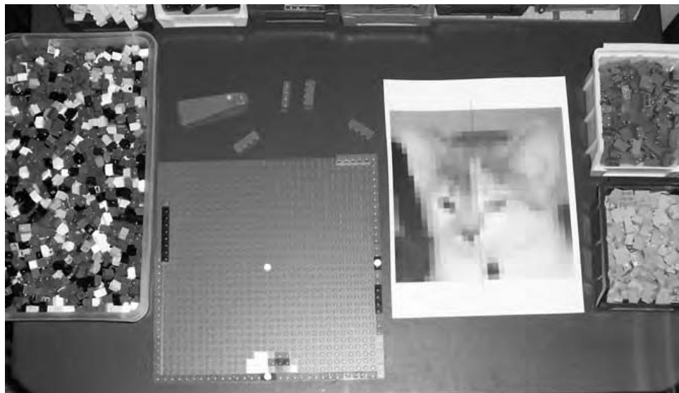
Figure 8-15: Everything you need to build a mosaic. Be sure you have lots of small elements like and handy.
Use each quarter on the printout to represent each quarter on the actual LEGO baseplate. In other words, if there is a light gray square in the very bottom left corner of the quartered section on the image, then make sure the bottom left corner of the baseplate gets a light gray element. Then look to see what color goes next to that piece and build up the mosaic accordingly.
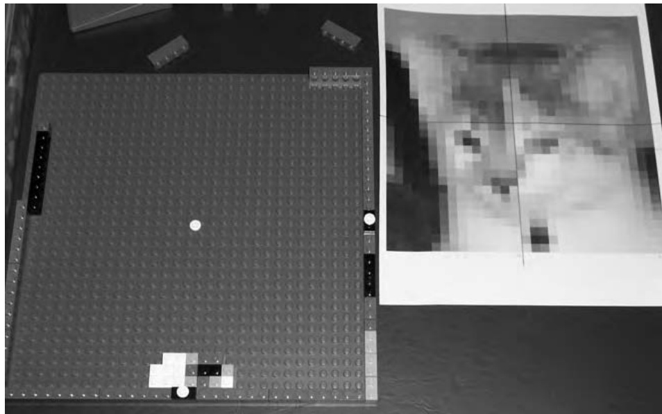
Figure 8-16: The white cylinder plate in the center of the baseplate represents the point on the photo printout at which the four quarter sections meet.
You may want to break your mosaic plan down into even smaller sections. You might try dividing each of the four sections into four more, for a total of sixteen. That way you aren’t trying to re-create the entire mosaic at once, but instead, you are working on small, manageable areas.
The result, when all the bricks are affixed to the baseplate, is a real life mosaic that looks more or less like the plan I started out with. And, as you can see in Figure 8-17, it looks pretty much like my original subject as well.
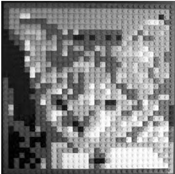
Figure 8-17: Izzy the kitten becomes Izzy the LEGO mosaic. Remember to step back a few feet and let your eyes see the bricks as one image and not as individual elements.
If your actual brick version of the mosaic doesn’t look as you intended it, don’t give up. Try setting it upright and stepping back. Look at the entire image and try to see what parts of it don’t seem to be sitting right with you. Then, go back and replace a few bricks at a time until the problem areas disappear.
Designing a Studs-Up Mosaic
As you saw earlier, a studs-up mosaic offers some subtleties that studs-out mosaics do not. Because you are using plates as seen from their side, rather than full-height bricks, you are obviously dealing with smaller changes in color and shape. Take another look at a studs-out versus a studs-up mosaic in Figure 8-18.
Although there’s nothing wrong with the letters in the studs-out mosaic, it’s also clear that the word LEGO is a little more natural looking in the studsup version. Being able to incorporate simple shading or highlighting techniques (such as seen above the letters on the studs-up version in Figure 8-18) gives you more control as a builder.
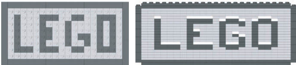
Figure 8-18: A side-by-side comparison of the two basic mosaic techniques. The studs-up version (on the right) offers some advantages when it comes to lettering.
Designing mosaics from a studs-up perspective isn’t really that much different than what you’ve already seen, but it does add more depth to the skills you are developing.
Design Grids for the Studs-Up Technique
Before you start this section, again refer to Appendix B of this book. This time, look for Design Grids #3 and #4. Both of these grids present LEGO elements from the side, as you would see them if you were holding a standard plate element between your fingers, like in Figure 8-19.

Figure 8-19: The plate view grids approach design work as though you are looking at a model from the side of the elements.
These plate view versions of the Design Grids take a different approach to planning LEGO models. For most models, they allow you to plan your work as seen from the side to help establish shapes and angles. When you use them to prepare a mosaic, they give you the ability to sketch out more subtle patterns than are typically possible with a studs-out approach. Take, for example, the simple sketch of the letter B shown in Figure 8-20.
It’s easy to see that the studs-up mosaic technique offers you the chance to include finer details on such things as letters. When used in a larger mosaic and viewed from a short distance, this letter will begin to appear almost hand drawn. You can compare that with the chunky lettering you saw back in Figure 8-1 when we were looking at the studs-out technique.
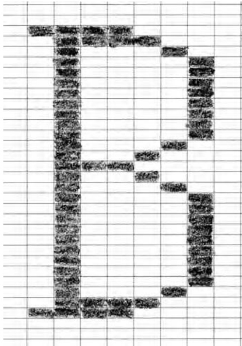
Figure 8-20: Serifs and gentle curving loops make this letter B an excellent subject for a studs-up mosaic.
Mosaics on Edge
Mosaic is a technique that lends itself to being turned on edge from time to time. Especially in those cases where you’ve used a plate view mosaic to spell out letters or even complete words, you may find things look better if you turn your work 90 degrees. For example, take a look at the small mosaic in Figure 8-21.
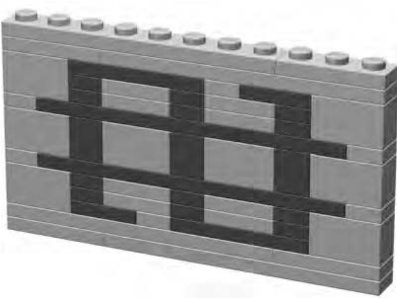
Figure 8-21: Alien writing? It could be, but keep reading to find out what it really is.
It may not look like much. In fact, when you first look at Figure 8-21 it’s hard to even tell what letter, if any, it’s supposed to be. Turn it 90 degrees and look at again. You’re likely to recognize the character now (see Figure 8-22).
The dollar sign, with its thin vertical lines, is much more recognizable when turned upright. But now there’s a problem. What do you do with a small mosaic like this when its studs are turned the wrong way? Rather than having to build an entire model turned on its side like this, you can easily incorporate this submodel into a larger work.
Let’s say you want a bank, or maybe even a casino, to add to your LEGO town. The dollar sign mosaic could be used to help indicate the nature of the building you’re constructing. In fact, with just a bit of planning, you could make the dollar sign part of the wall of the building, as you see in Figure 8-23.
You can see that I’ve built a portion of the wall surrounding the dollar sign mosaic to give you an idea what the final model might look like. Of course, you’re probably wondering, “What makes it stay in like that?” The answer is a bit of geometric trickery that is surprisingly easy to accomplish.
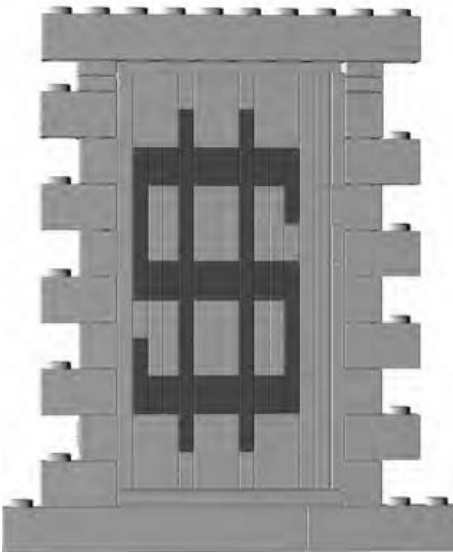
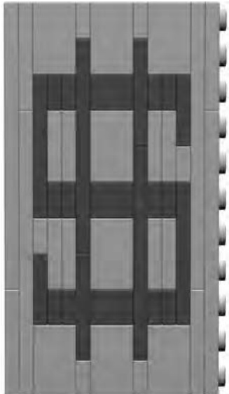
Figure 8-22: Turning a letter or symbol the Figure 8-23: At close range, you will be right way makes it easier to read. But how able to see the different orientations of the do you add it to a model where the other bricks and plates. From a short distance bricks are pointing in different directions? away, however, your model takes on a more uniform and realistic look.
What you don’t see in Figure 8-23 are the two Technic bricks, one on either side that are helping to hold the mosaic section in place. To give you a better idea of what’s really going on, I have created some close-up images of this wall example. In Figure 8-24, you can see that the right side of the mosaic is supported by a plate (shown in black) that fits perfectly into one of the two Technic bricks. The plate is oriented vertically, like the rest of the mosaic, whereas the Technic brick is oriented with its stud up, just like the rest of the main wall.
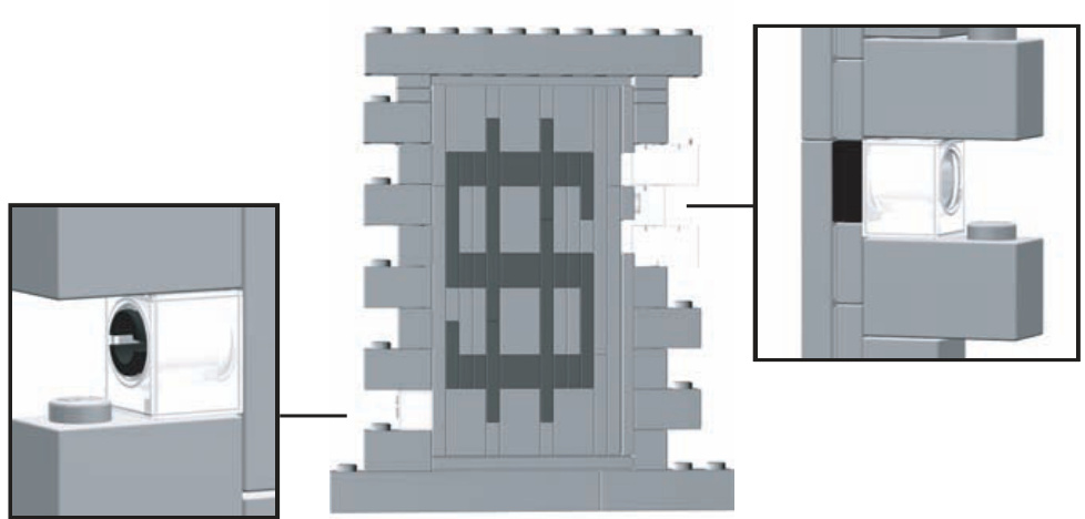
Figure 8-24: Mixing Technic bricks with regular system parts offers some amazing construction possibilities.
The left side of the mosaic (as seen in Figure 8-24) is supported by a Technic pin (shown in black) coming out of the other Technic brick and into the bottom of the plate next to it. Once again, the Technic brick is oriented with its stud facing up, whereas the plate to its right is turned 90 degrees just like the rest of the mosaic-related pieces. The result, when viewed from even a short distance, is that the mosaic section is really just part of the wall. The delicate lines that form the dollar sign become natural looking and easy for the eye to read.
Review: Mosaics of All Sizes and Shapes
As I noted earlier in the chapter, there is no one right size or shape for a mosaic. Instead, the technique can be applied to complete pictures (like the one of Izzy shown in Figure 8-17) or can be a much smaller arrangement of pieces that you use to embellish a model (like the dollar sign example just discussed).
If you add a mosaic section to a larger model, the work will display itself. If you decide to try your hand at an image, be sure to show it off once you’re done, like in Figure 8-25. Let people know what interests you, and show them how you’ve captured that in LEGO pieces.
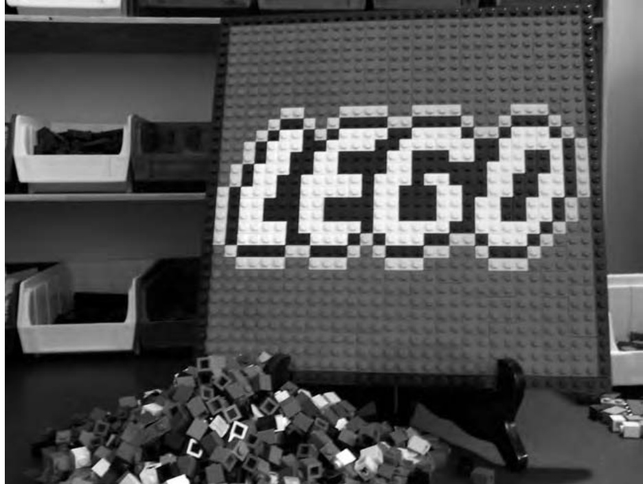
Figure 8-25: Of course, if you haven’t noticed already, it’s worth pointing out that the LEGO name itself makes for a great mosaic subject.
There is no one rule to guide you in determining how large a mosaic should be or which of the two basic techniques you should use. Let the requirements guide your decisions. If you need to spell out a company name on the side of a building, then build your mosaic letters to an appropriate size. If, on the other hand, you’re creating a portrait of a favorite relative, be sure to make it large enough to capture their entire personality.
9
T E C H N I C : N O T A S T E C H N I C A L A S I T M A Y S E E M
The last chapter began by asking the question, “What is a mosaic?” To kick off this chapter, you might find yourself asking a similar question, “What is Technic?” In order to find that answer, let’s first look at a little bit of LEGO history.
In 1977, the LEGO company released an exciting new line of products known then as the Technical Sets. The name soon changed to the Expert Builder series and then morphed yet again to become known simply as Technic. These sets contained the standard bricks and plates with which we are still familiar, but in addition, they also contained things like gears, axles, and bricks with holes that you could lock together with pins. For the remainder of the chapter, I simply refer to this genre as Technic in keeping with its current name.
Figure 9-1 shows one of the first models to be released that premier year in the Technic sets series.
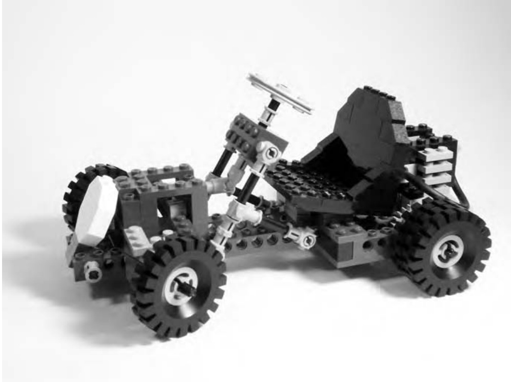
Figure 9-1: This Technic go-kart was one of the very first in a series of more complicated sets that introduced gears and other new elements to the LEGO system.
Set #948 (#854 in Canada and Europe) was a rugged little go-kart with a one-cylinder motor. It was not a working engine, but rather a collection of plates and other parts arranged to resemble a motor. The steering on the kart did work though. In Figure 9-1, you can see that the wheels on the front of the vehicle are turned slightly. This is thanks to the rack-and-pinion steering made up from some of the new Technic parts that were introduced. The set design shows what you could do with just 200 pieces and a little imagination.
Part of what made these new models even more exciting—beyond the new types of LEGO elements they contained—was the fact that they were still compatible with traditional bricks, plates, and slopes.
That compatibility of standard system parts with basic Technic pieces is the main focus of this chapter. You’ll start by examining some of the Technic parts in greater detail. I’ll follow this with an explanation of some simple assembly tips. Finally, you’ll see how some of these techniques can be incorporated into a small Technic model.
It’s important to point out, however, that this chapter is really just an overview of the Technic system. The nature of the parts and the ways in which you can use them offer you the ability to create complicated models and projects that are beyond the scope of this book. If you’re planning on getting heavily into Technic building, I suggest that you look at other books that are available; specifically those related to building LEGO Mindstorms models. The Mindstorms system is an enhancement to traditional Technic that LEGO introduced in 1998. It includes a programmable brick that can interact with your home computer allowing you to build robots and other sophisticated machines. Also, books about Mindstorms typically include lots of good techniques and ideas that can apply to Technic models that don’t use the programmable element.
NOTE For a list of links to books about the Mindstorms system that may also contain advanced Technic building techniques, visit www.apotome.com/links.html.
Technic: A System Within a System
I first discussed the idea of a system back in Chapter 1. I described a system as a collection of different bits and pieces, and also the ways in which they connect with each other to become a larger object or series of objects. For the purposes of this book, think of Technic pieces as a subset of the larger LEGO system you’ve already studied. A subset is just a smaller group of something set apart from a larger group by one or more differences.
In the case of Technic, the difference is that these elements are primarily oriented toward creating machines, and the smaller components within them, or structures—not in using the standard brick connections you’re used to. For instance, you could use Technic pieces to help you build a crane (an example of a machine), or you could use them to build a bridge (an example of a structure).
Technic Pieces: An Overview
To give you a better idea of what Technic pieces look like, I’ve included illustrations of some of the most common elements from this category. A separate complete overview of the Technic subset appears in Appendix A (the Brickopedia). The pieces shown in this chapter give you an overview of the types of elements described as being Technic pieces.
NOTE You may find that your own LEGO collection doesn’t include a large number of the parts described in the following pages. That might lead you to wonder, “Where can I get more Technic parts if I need them?” There is no one perfect answer, but here are a couple of suggestions. First, go to the official LEGO website (www.lego.com) and look for sets that carry the Technic label. Or, you can look on the website for this book (www.apotome.com/ links.html) and find up-to-date links to current sets that also contain some Technic-style parts. Building up a stock of Technic parts can take time, but the added flexibility they bring to your models is worth the effort.
The images that follow show the range of sizes in which LEGO Technic pieces have been made. I’ve included images for many of the most common Technic elements, though many more exist that I’ve not recorded here. An explanation of the cataloging technique used for these entries is available at the beginning of Appendix A.
Bricks
Technic bricks are very much like the standard bricks you first saw back in Chapter 1. The primary difference is that Technic bricks have holes running through them that allow you to connect them to gears or other bricks via pins or axles. You can see a Technic brick next to a standard brick in Figure 9-2.
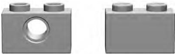
Figure 9-2: A Technic on the left compared to a standard on the right. Note the hole running through the brick and the hollow studs. These help define the look of Technic brick elements.
Technic bricks, just like standard bricks, come in a variety of sizes from as small as to as long as . A few samples are shown in Figure 9-3.
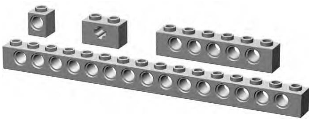
Figure 9-3: An assortment of various Technic bricks
It’s interesting to note that most Technic bricks are designed with the holes centered between the studs on top. The most notable exceptions to that rule are the and the with two holes. You can see each of these pieces in Figure 9-4.
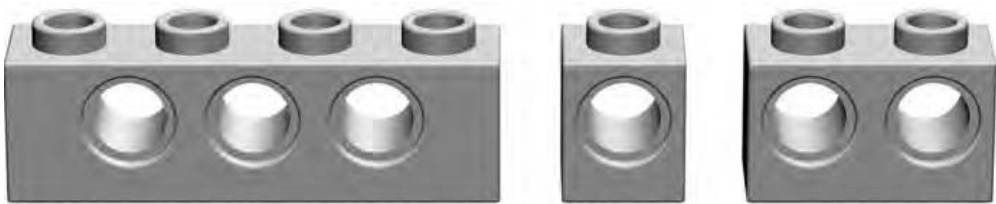
Figure 9-4: Compare the with the other two parts shown here. The and have holes located directly below the studs rather than centered between them.
Studless Beams and Lift Arms
It’s easy to see the similarities between Technic bricks and beams. Both are long, thin elements with holes in the sides. There are, however, differences between them that make it worth differentiating between the two. Whereas bricks have traditional studs on top, beams do not.
Technic bricks come in only one width, whereas beams come in a square full-width variety and also a thinner half-width version. That means that while Technic bricks have the same geometry as standard bricks, full-width beams are a squarish shape when you view them from the end and half-width ones are significantly thinner. In Figure 9-5, you can see a brick sitting behind each of the two styles of beam.
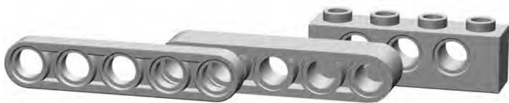
Figure 9-5: A half-width beam sits in front of a full-width beam that in turn sits in front of a Technic brick.
Beams began appearing in Technic sets in the late 1990s. They opened the door to models that used studless building techniques. This is a general term applied to any combination of parts that are held together in ways other than the traditional stud/tube connection. In the case of Technic beams, this usually means that they are attached to one another using pins or axles. I’ll talk more about those pins in a minute, but for now you can see a simple example of studless construction in Figure 9-6.
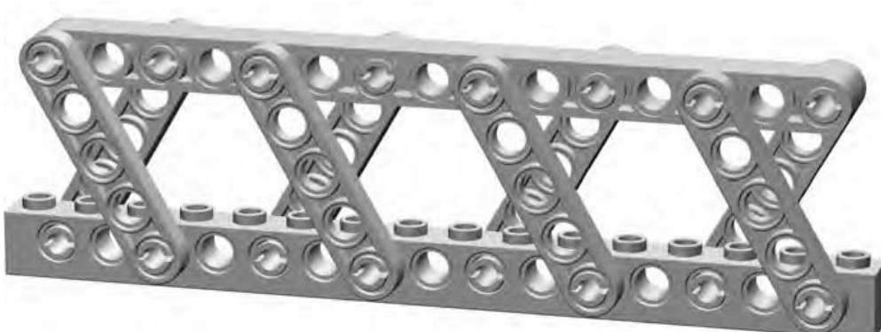
Figure 9-6: You could use a technique like this to produce part of a bridge or maybe the boom on a large crane.
The rounded look of studless construction adds a sense of realism, although some builders still prefer to work with the traditional studded Technic bricks instead of the newer beams.
Gears
In many ways, LEGO Technic gears are identical to gears you find in everyday objects such as bicycles, cars, or even old-fashioned grandfather clocks. The only real difference, of course, is that LEGO gears can be attached to and used with other LEGO pieces. Figure 9-7 shows a small sample of some of the many sizes of LEGO gears that are available.
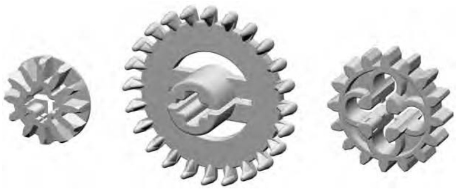
Figure 9-7: An assortment of various Technic gears
I’ll talk more about how gears work later in the chapter when I discuss assembly ideas.
Pins/Axles
Earlier I noted that Technic bricks have holes that run through them. Those holes were obviously created for a reason—namely, to enable you to connect the bricks to each other and to other pieces (using pins) and to also allow you to attach things like gears or wheels to the bricks (using axles and/or pins). To allow for such a variety of connections, pins and axles come in an equal number of configurations, some of which are shown in Figure 9-8.
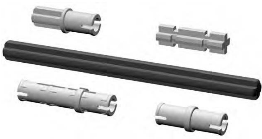
Figure 9-8: An assortment of various pins and axles
Bushings
Once you’ve inserted a Technic axle through the hole in another Technic element, you will most likely want to secure it with something. A bushing is a tight-fitting collar that slides onto an axle with enough friction to keep it from flying off when the axle spins. Although bushings don’t lock completely tight (like nuts and bolts) they do go a long way toward keeping your axles in place.
You can see a simple example, showing a bushing in use, later in the chapter when we look at the helicopter model. For now, take a look at the half-width and full-width bushings versions in Figure 9-9.
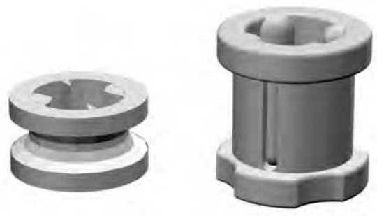
Figure 9-9: Here are two fairly simple looking pieces, but don’t let their plain looks fool you into thinking they’re not important elements.
Couplers
There may be situations that arise where you want to connect Technic axles for aesthetic and/or functional reasons. Coupler elements allow you to join axles together at a variety of angles. They may have an opening that holds an axle firmly (like the opening facing front on the leftmost part in Figure 9-10), or they may have openings like Technic bricks that allow axles or pins to spin (like the opening on the bottom of the rightmost part in Figure 9-10).
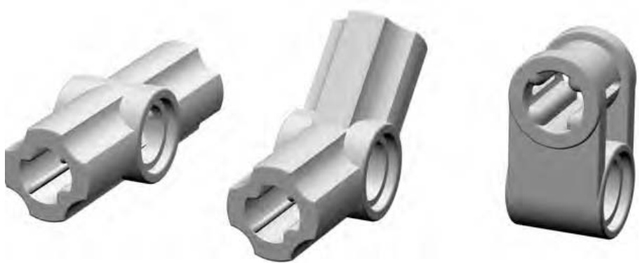
Figure 9-10: An assortment of various couplers
I mentioned features on most couplers that allow axles and/or pins to rotate or, by contrast, for axles to be held tightly and prevented from spinning. Figure 9-11 demonstrates the basic difference in these two attributes.

Figure 9-11: Rotating versus nonrotating openings in Technic couplers. The part on the left allows the axle to spin if needed, while the piece on the right keeps it from doing any spinning at all.
As noted in the part descriptions earlier, many pieces have one or both of these features. That is, some have an opening that allows an axle to rotate easily while that same piece may or may not also have an opening that fits an axle exactly and does not allow rotation. Finding the right coupler for the right task is always an interesting challenge when you are building with Technic parts.
Getting Started with Technic: Assembly Notes
As noted earlier, there are many wonderful books already on the market that deal with building complex Technic-style models, especially those incorporating the LEGO Mindstorms programmable brick system. Rather than try to re-create any of those advanced techniques in this book, I have decided instead to provide you with a handful of basic assembly tips and tricks that you can apply to almost any model regardless of the percentage of Technic pieces it contains.
Just as with regular system pieces, there are no right or wrong ways to assemble Technic elements. There are, however, some interesting combinations that might be worth pointing out.